Automatic light intensity control equipment and method in liquid crystal display equipment
A technology of automatic brightness control and brightness control, applied in static indicators, components of color TVs, components of TV systems, etc., can solve the problems of increased power consumption, increased brightness, and the inability of the picture to be very bright.
- Summary
- Abstract
- Description
- Claims
- Application Information
AI Technical Summary
Problems solved by technology
Method used
Image

Examples
Embodiment 1
[0040] The LCD device according to the present invention automatically controls the brightness of the backlight according to the duty ratio signal generated in proportion to the average gray level of pixels to be displayed in the LCD device.
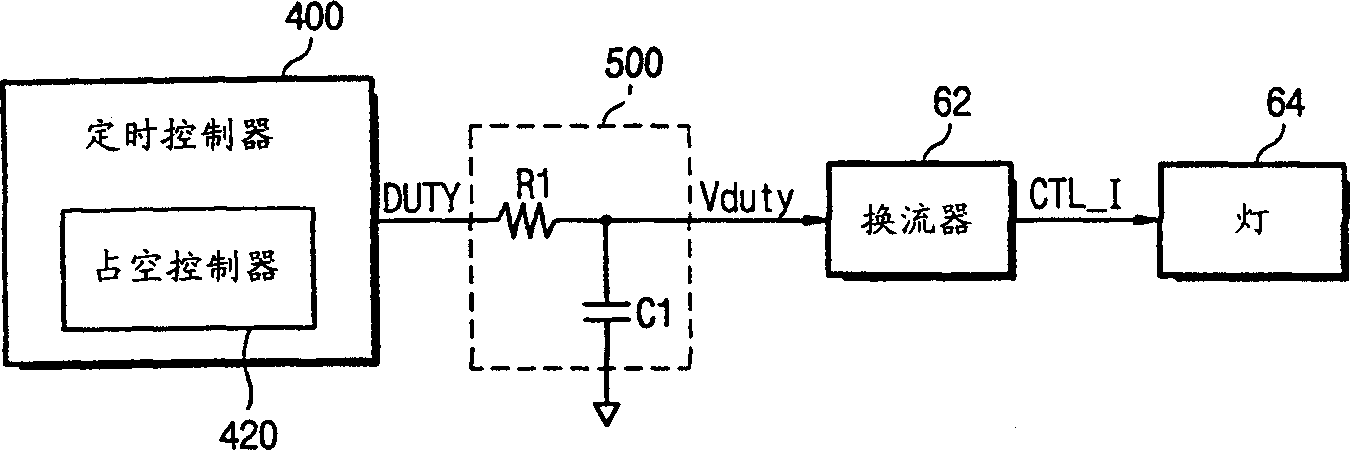
[0041] image 3 It is a block diagram showing the brightness control scheme of the LCD module backlight according to the first preferred embodiment of the present invention, which is applied to a portable computer or a desktop computer. refer to image 3 , the LCD module includes a timing controller 400, including a duty controller 420, which is used to calculate the average value of the gray level in a horizontal line period, that is, 1H, for a picture or frame to be displayed on the LCD module, and generating a duty ratio signal DUTY corresponding to the calculated gray scale average; and an R-C circuit 500 for summing the duty ratio signal DUTY generated from the timing controller 400 in units of 1H during one frame, and The variabl...
Embodiment 2
[0057] According to another aspect of the present invention, the LCD module controls the backlight by generating a variable brightness control voltage having a duty cycle corresponding to the color state of the pixel data from the duty controller, and responding to the variable brightness control voltage, i.e. The current intensity of the fluorescent lamp automatically controls the brightness of the backlight. Alternatively, the LCD module may be arranged to generate a variable brightness control with a duty cycle corresponding to the average gray level of the pixel data from the duty controller, and the color state of the pixel data as described with reference to the first embodiment. Voltage.
[0058] refer to Figure 7 , add the brightness values of green (G), red (R) and blue (B) together to get the brightness value of white. For example, if the luminance values of the three colors are 73.62, 29.45, and 21.24, respectively, then the total luminance value of white is ...
Embodiment 3
[0084] The LCD module of the present invention can perform user-requested brightness control and automatic brightness control for each picture. To this end, the LCD module of the present invention includes a merged circuit that accommodates these two control functions without conflict. The structure of the LCD module including the merging circuit will now be described.
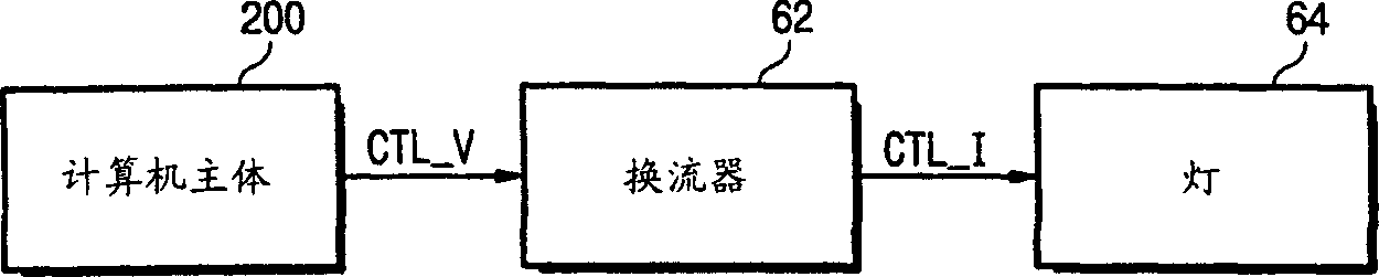
[0085] Figure 11 is a block diagram showing the backlight brightness control scheme of the LCD module according to the third embodiment of the present invention when it is used as a display device in a portable computer or a desktop computer. Referring to the drawings, in addition to responding to the brightness control voltage CTL_V generated by the CPU of the computer or the main body 200 and the duty ratio signal DUTY generated by the duty controller 420 in the timing controller 400, a variable brightness control output from the R-C circuit 500 is generated. voltage Vduty outside of the combining circuit...
PUM
 Abstract
Description
Claims
Application Information
 - R&D Engineer
- R&D Manager
- IP Professional
- Industry Leading Data Capabilities
- Powerful AI technology
- Patent DNA Extraction
Browse by: Latest US Patents, China's latest patents, Technical Efficacy Thesaurus, Application Domain, Technology Topic.
© 2024 PatSnap. All rights reserved.Legal|Privacy policy|Modern Slavery Act Transparency Statement|Sitemap