
Radio receiver and radio receiving method

A wireless receiving device and receiver technology, applied in the direction of electrical components, transmission systems, amplification control, etc., can solve the problem of inability to perform correct demodulation, inability to correctly demodulate the data part, and inability to correctly estimate the phase change of the data part and amplitude changes

Inactive Publication Date: 2002-08-07
PANASONIC CORP
View PDF2 Cites 4 Cited by
  • Summary
  • Abstract
  • Description
  • Claims
  • Application Information

AI Technical Summary

Problems solved by technology

[0004] Thus, correct demodulation cannot be performed if clipping occurs
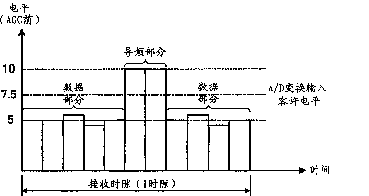
Since the pilot part is used to estimate propagation path characteristics, when clipping occurs due to the pilot part, the phase fluctuation and amplitude fluctuation of the data part cannot be accurately estimated and compensated. As a result, not only the pilot part but also the data part cannot demodulate correctly

Method used


Image

  • Radio receiver and radio receiving method
  • Radio receiver and radio receiving method
  • Radio receiver and radio receiving method

Examples


Embodiment 1

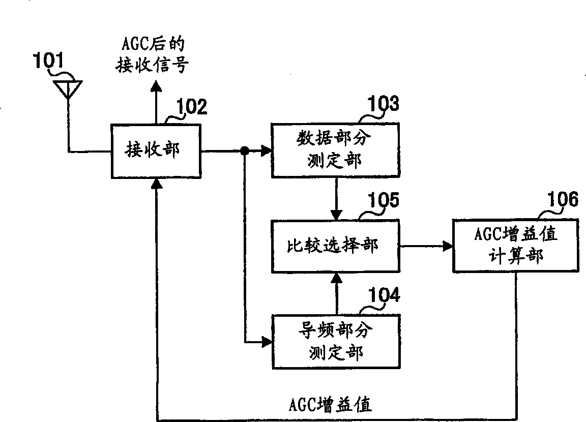
[0014] figure 1 A block diagram showing the configuration of the wireless receiving apparatus according to Embodiment 1 of the present invention. exist figure 1 In the wireless receiving device shown, the receiving unit 102 performs predetermined receiving processing such as down-conversion on a signal received through the antenna 101 . The signal after the reception processing is output to the data portion measurement unit 103 and the pilot portion measurement unit 104 .

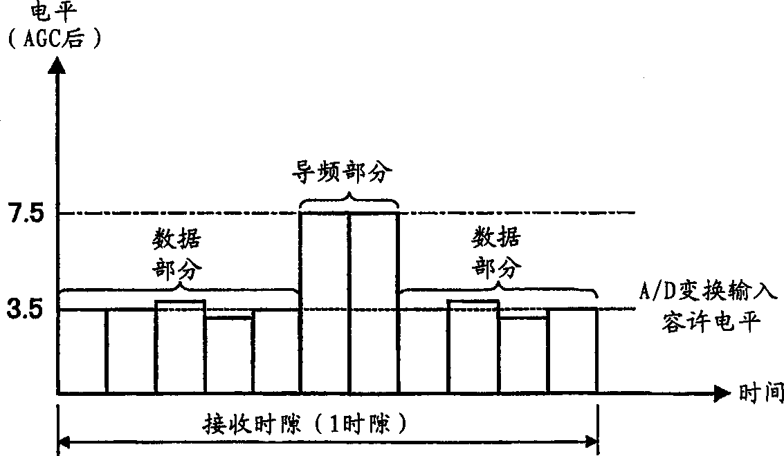
[0015] The reception unit 102 adjusts the level of the received signal based on the AGC gain value (level control value) calculated by the AGC gain value calculation unit 106 described later. That is, the receiving unit 102 performs AGC on the received signal. With this AGC, the level of the received signal falls within the input allowable range of the A / D conversion. A detailed description of the AGC will be described later.

[0016] The data portion measurement unit 103 measures the reception level o...

Embodiment 2

[0032] The reception level of the pilot portion and the reception level of the data portion may differ or be the same depending on communication conditions. For example, in the CDMA / TDD system, in the case of using a common pilot for each communication partner, since the level of the pilot part is constant regardless of the number of code multiplexes, the level of the pilot part is constant by changing the number of code multiplexes. difference in the receiving level of the receiver. On the other hand, when the pilot of the same level as the level of the data part is transmitted to each communication partner, since the level of the pilot part changes according to the change in the number of code multiplexing, even if the number of code multiplexing changes, The reception level is also the same for both.

[0033] When the reception levels of both are different, by performing AGC as in the first embodiment above, clipping can be prevented from occurring. However, when the rece...


PUM


Abstract

A data portion measuring section 103 measures a reception level of a data portion of a received signal, and a pilot portion measuring section 104 measures a reception level of a pilot portion of the received signal. A comparing / selecting section 105 compares the reception level of the data portion with that of the pilot portion, and selects a higher reception level. An AGC gain value calculating section 106 calculates an AGC gain value from the higher reception level selected by the comparing / selecting section 105 and an input allowable level of A / D conversion.

Description

technical field [0001] The present invention relates to a wireless receiving device and a wireless receiving method, in particular to a wireless receiving device and a wireless receiving method that perform automatic gain control (AGC: Auto Gain Control) on a received signal. Background technique [0002] As the conventional AGC, as disclosed in Japanese Patent Application Laid-Open No. 8-274558, by using two kinds of time constants, it is possible to follow the gradual change in the level of the received signal due to fading. In addition, conventional AGC is performed based on the average level of one slot of the received signal. [0003] However, when AGC is performed based on the average level per slot, if there are data parts and pilot parts (known signal parts) with different reception levels in one slot, the optimal AGC may not be calculated. The problem of gain value. That is, in a TDD (Time Division Duplex: Time Division Duplex) wireless c...

Claims


Application Information

Patent Timeline
Patent Type & Authority Applications(China)
IPC IPC(8): H03G3/00H03G3/30
CPCH03G3/3052H03G3/005H04B1/10
Inventor 藤井英夫
Owner PANASONIC CORP
Learn More