Elastic boring bar

An elastic and boring bar technology, which is applied in the direction of boring bar, boring machine/drilling machine parts, drilling/drilling equipment, etc., can solve the problem that the boring bar cannot automatically adjust the tool, and achieve the effect of automatic tool adjustment

Inactive Publication Date: 2002-08-21
HUAZHONG UNIV OF SCI & TECH
View PDF1 Cites 7 Cited by
  • Summary
  • Abstract
  • Description
  • Claims
  • Application Information

AI Technical Summary

Problems solved by technology

However, the boring bar cannot automatically adjust the tool to meet the needs of the size adjustment of the machining hole

Method used


Image

  • Elastic boring bar
  • Elastic boring bar
  • Elastic boring bar

Examples


Embodiment Construction

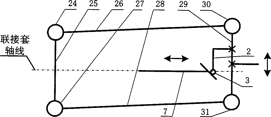
[0012] The present invention will be further described below in conjunction with the accompanying drawings.

[0013] exist figure 1 Among them, the first connecting rod 25 is a simplified body of the coupling sleeve and the rear section of the elastic deformation body, the second and fourth connecting rods 26, 28 are respectively simplified bodies of the upper and lower parts of the middle section of the elastic deformation body, and the third connecting rod 29 is an elastic body. The simplified body of the front section of the deformable body, the first to the fourth hinges 24, 27, 30, 31 are respectively simplified bodies of four thin walls parallel to each other of the elastic deformable body, and they constitute a parallelogram four-bar linkage mechanism.

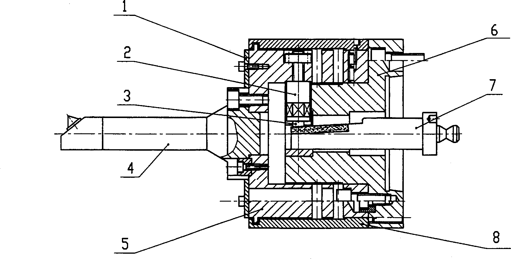
[0014] Such as figure 2 Shown, the present invention can be divided into rod body and the cutter bar two parts that are connected with it that boring tool is housed, and rod body is made of elastic deformation body 5,...


PUM


Abstract

The elastic boring bar includes a bar body and a cutter bar with boring cutter connected to the bar body. The bar body consists of a cylindrical elastic deformation body with longitudinal grooves andhorizontal grooves, a cylindrical connection sleeve inside the elastic deformation body and is fixed and connected to the back section of the elastic deformation body coaxially, a push bar with top end fixed and connected to the front section of the elastic deformation body, a drawing bar below the push bar and a steel ball inside the hole in the lower end of the push bar. The cutter bar has an end connected to the front section of the elastic deformation body. The boring bar can be used to perform minute quantity compensation of cutter(s).

Description

technical field [0001] The invention relates to a boring bar for a special boring head, in particular to an elastic boring bar, which can realize automatic tool adjustment in the boring process, that is, error compensation. Background technique [0002] In the boring process, especially when a large number of boring processes are carried out on the automatic production line, due to the existence of certain or uncertain factors such as tool wear and adjustment, machine tool wear and other process conditions, the size error of the processed hole ( Size dispersion) increases, for this reason, it is necessary to adjust the boring tool during processing to reduce the size error of the processed hole. The existing manual tool adjustment method not only cannot guarantee the accuracy of tool adjustment, but also interrupts the normal working rhythm of the automatic line, and at the same time increases the labor intensity of workers, which greatly affects the quality, efficiency and ...

Claims


Application Information

Patent Timeline
Patent Type & Authority Applications(China)
IPC IPC(8): B23B29/02B23B47/00
Inventor 邓建春李培根邵新宇邹香云
Owner HUAZHONG UNIV OF SCI & TECH
Why Eureka
Try Eureka