Dye laser structure based on guided mode resonance effect

A dye laser and guided mode resonance technology, which is applied to the structure/shape of lasers, optical resonators, and laser components, can solve the problems of increasing the complexity of the optical path and unfavorable detectors for signal collection.

Pending Publication Date: 2021-09-07
YANGZHOU UNIV
View PDF0 Cites 2 Cited by
  • Summary
  • Abstract
  • Description
  • Claims
  • Application Information

AI Technical Summary

Problems solved by technology

However, the emission direction of this type of laser is related to the photon band gap. The laser emission direction is mostly reflection, which will increase the complexity of the optical pa

Method used


Image

  • Dye laser structure based on guided mode resonance effect
  • Dye laser structure based on guided mode resonance effect
  • Dye laser structure based on guided mode resonance effect

Examples


Embodiment 1

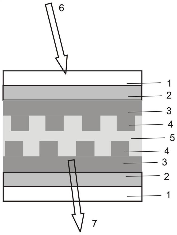
[0022] Embodiment 1: select two transparent quartz glass substrates 1 of identical size, prepare low-refractive-index film 2 on substrate, as porous silicon etc., the thickness of low-refractive-index film 2 is greater than 1 micron; After this, in low-refractive-index film On top of 2, uniform waveguide layer 3 and grating 4 are prepared. The uniform waveguide layer 3 and grating 4 are composed of the same material, both of which are oxides with high refractive index, such as titanium oxide, tantalum oxide, etc. The structural parameters prepared on the two substrates It is exactly the same; finally, the organic laser dye IR140 is dissolved in a polyurethane solvent, and is prepared in the middle of the two gratings by spin coating, etc., to form the structure involved in the present invention, such as figure 1 shown.

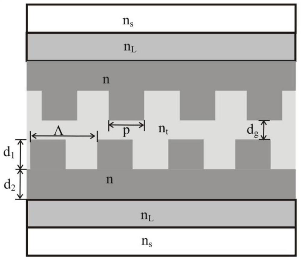
[0023] Structure parameters such as figure 2 As shown, the resonant peak of the transmission guided mode will be located at 820nm: the refractive index of t...

Embodiment 2

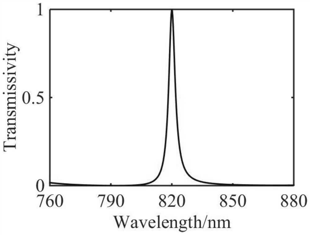
[0024] Example 2: The only difference from Example 1 is that the parameters of the structure are different. The transmission resonance peak is located at 870nm: the refractive index of the grating material and the waveguide layer material are both n=2.4, the period Λ=614nm, and the depth of the grating groove is d 1 =260nm and grating width p=184.2nm, waveguide layer thickness is d 2 =60nm. The gap thickness of the two grating structures is d g =320nm, the refractive index of the low refractive index film is n s =1.1, the refractive index of the middle layer is n t =1.3, the refractive index of the glass substrate is n s =1.46. When the laser dye IR140 is not added, the broad spectrum is incident on the structure composed of the above parameters, resulting in a guided mode resonance transmission peak at 870nm, such as Figure 5 As shown, this peak matches the emission wavelength of the near-infrared laser dye IR140. If the organic laser dye IR140 is dissolved in a polyur...


PUM

PropertyMeasurementUnit
Thicknessaaaaaaaaaa
Thicknessaaaaaaaaaa

Abstract

The invention discloses a dye laser structure based on a guided mode resonance effect, which can realize output enhancement of near-infrared laser in a transmission direction. The structure is composed of upper and lower layers of independent, parallel and opposite guided-mode resonance gratings and organic dye, each of the upper and lower layers of guided-mode resonance gratings is composed of a surface grating, a thin-film waveguide layer, a low-refractive-index thin-film layer and a glass substrate, and the structure parameters are the same. An organic laser dye located between the two grating structures is dissolved in the polyurethane solvent. When no organic laser dye is added in the structure, transmission-type guided-mode resonance can be realized, and the resonance wavelength is equal to the pumping light wavelength or the emission light wavelength of the laser dye; after the organic laser dye is added, pump light enters the structure at a certain angle, when the pump energy is higher than the threshold working energy of the laser, the laser emits laser perpendicular to the surface of the glass substrate, and the emitted laser is enhanced in the transmission direction.

Description

technical field [0001] The invention relates to a dye laser structure based on the guided mode resonance effect, in particular to a structure capable of realizing laser output in the transmission direction. Background technique [0002] Due to their unique properties, nanolasers and plasmonic lasers have potential applications in the field of integrated optical circuits, and have attracted more and more researchers' attention in recent years. Different nanoplasmonic laser structures have been developed successively, such as metal-covered cylinders, nanorings, silver-coated semiconductor nanowires, gold-coated microspheres, etc. Plasmon lasers have unique surface plasmons, especially compact sub-wavelength structure, ultra-fast dynamic response, etc. However, this kind of device has a large metal loss in the optical frequency band. [0003] In addition to plasmonic lasers, photonic crystal lasers have also attracted much attention in recent years. Photonic crystal lasers ar...

Claims


Application Information

Patent Timeline
IPC IPC(8): H01S3/08H01S3/213G02B6/124
CPCH01S3/213H01S3/08G02B6/124
Inventor 王康妮崔涛许亚芳
Owner YANGZHOU UNIV
Why Eureka
Try Eureka