Check patentability & draft patents in minutes with Patsnap Eureka AI!

Horizontal electric connector

一种电连接器、横置式的技术,应用在绝缘外壳的保持构造领域,能够解决连接不良、抵靠面不一致、短路等问题,达到防止连接不良与短路、防止短路的效果

Inactive Publication Date: 2002-10-16
JST MFG CO LTD
View PDF1 Cites 2 Cited by
  • Summary
  • Abstract
  • Description
  • Claims
  • Application Information

AI Technical Summary

Problems solved by technology

Therefore, the feet are easily deformed when subjected to external forces.
Once the foot is deformed, the abutment surface with other second electrical contacts becomes inconsistent, so that coplanarity cannot be obtained, or problems such as poor connection and short circuit occur

Method used


Image

  • Horizontal electric connector
  • Horizontal electric connector
  • Horizontal electric connector

Examples


Embodiment Construction

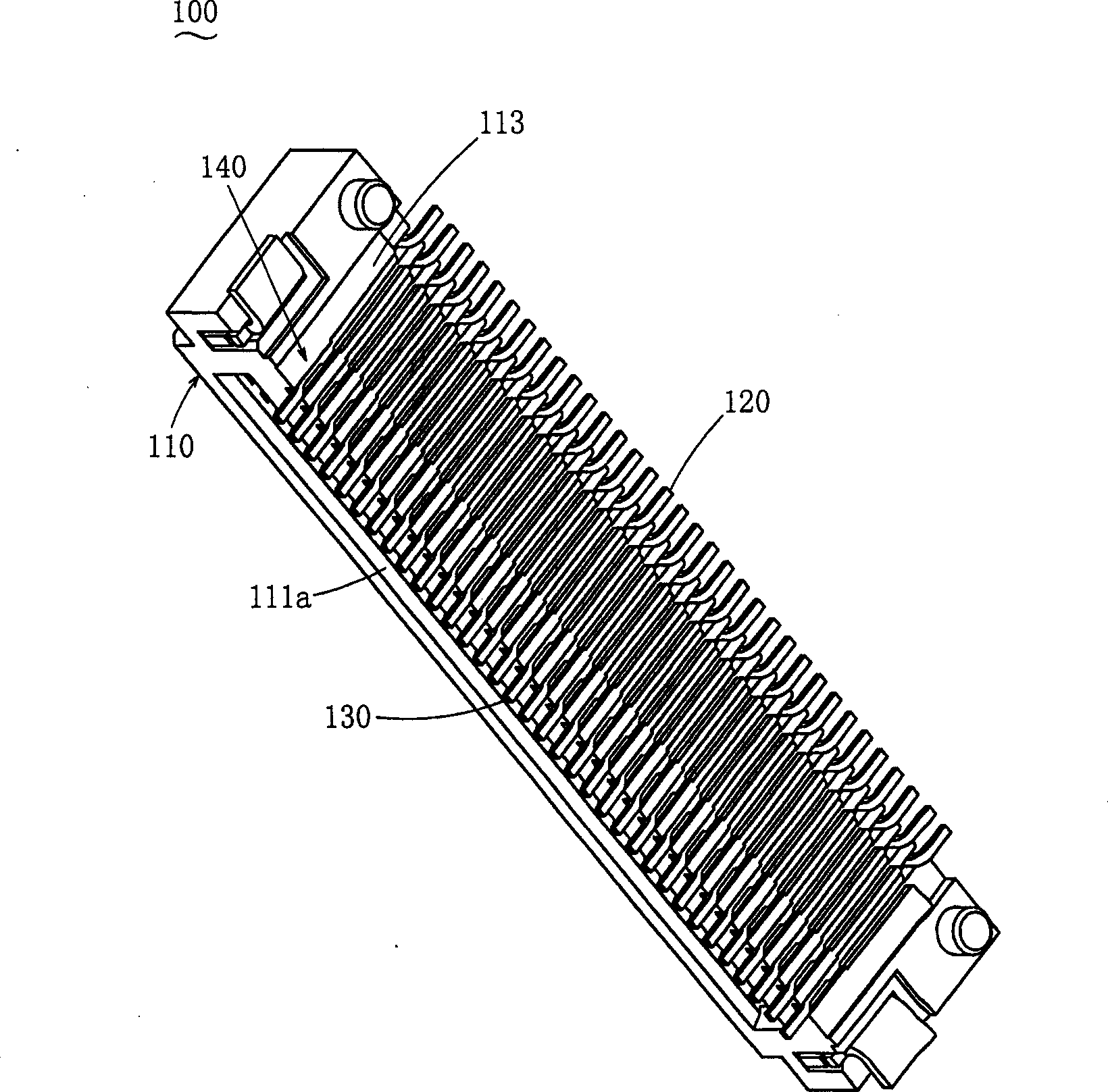
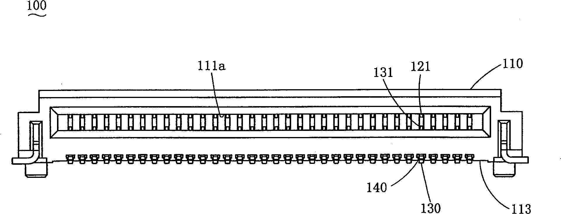
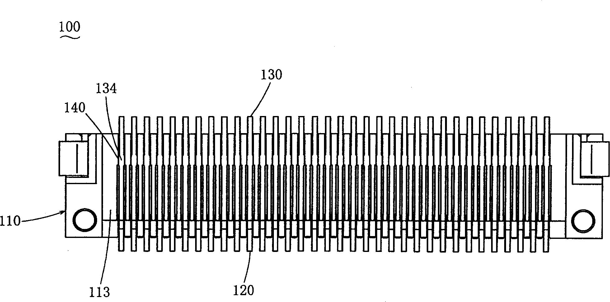
[0020] Examples of the present invention are described below. Figure 1~4 is the horizontal type electrical connector 100 of the illustrated embodiment. The horizontal electrical connector 100 is a card edge connector installed horizontally on the printed wiring board 200, and an IC card or the like is inserted into the printed wiring board 200 from an opening-shaped insertion port on one side thereof in a direction substantially parallel to the printed wiring board 200. front end.

[0021] exist Figure 1~4 Among them, 110 is an insulating case formed of an insulating material such as resin. Here, the insulating housing 110 forms a receiving portion 111 . The receiving portion 111 has an opening shape toward the rear. A receiving hole 111A communicating with the housing portion 111 and receiving an IC card or the like is formed in the front portion of the insulating case 110 . In this insulating case 110 , the first electrical contact 120 and the second electrical contac...


PUM


Abstract

The invention relates to a horizontal electrical connector (100), comprising: an insulating shell (110); a contact portion (121) which is pressed into the insulating shell from the rear side and contacts a conductive portion on the other side; Part (121) extends from the rear side of the insulating housing (110) to expose the first electrical contact (120) of the foot (122) that descends; it is fixed at a lower position than the first electrical contact (120) The contact portion (131) in the insulating case (110) and in contact with the opposite side conductive portion, and thus the contact portion (131) extends from the rear side of the insulating case (110) and is exposed along the bottom surface of the insulating case (110) ( 113) The second electrical contact (130) of the foot (132) facing forward; it is arranged on the bottom surface (113) of the insulating shell (110) and is formed by the rear of the foot (132) of the second electrical contact (130). The foot support part (140) pressed in from the side can prevent deformation of the foot of the second electrical contact.

Description

【Technical field】 [0001] The invention belongs to the technical field of horizontally installing electrical connectors on printed circuit boards and the like, and relates to a holding structure for an insulating shell of an electrical contact. 【Background technique】 [0002] The following horizontal electrical connectors are well known (for example, refer to Japanese Patent Application Publication No. 1-160679). And the first electrical contact of the foot portion that extends from the contact portion to be exposed from the rear side of the insulating housing and then descends; it has a contact that is fixed to the insulating housing at a lower position than the first electrical contact and contacts with the contact on the opposite side portion, and thus the contact portion extends from the rear side of the insulating housing to expose the second electrical contact of the foot along the bottom surface of the insulating housing towards the front. This horizontal electrical c...

Claims


Application Information

Patent Timeline
Patent Type & Authority Applications(China)
IPC IPC(8): H01R12/55H01R12/71H01R13/40H01R13/41H01R13/46
CPCH01R12/716H01R12/721H01R13/41H01R13/46
Inventor 黑田桂治宫本大智
Owner JST MFG CO LTD
Features
  • R&D
  • Intellectual Property
  • Life Sciences
  • Materials
  • Tech Scout
  • Unparalleled Data Quality
  • Higher Quality Content
  • 60% Fewer Hallucinations
Learn More