Control module for system state display

A technology for displaying control modules and system status, applied in hardware monitoring, instruments, electrical and digital data processing, etc., can solve problems such as system damage, burned CPU, abnormal, if not detected in time, to achieve the effect of protection and safety

Inactive Publication Date: 2002-11-27
SOYO COMP
View PDF0 Cites 16 Cited by
  • Summary
  • Abstract
  • Description
  • Claims
  • Application Information

AI Technical Summary

Problems solved by technology

What's more, DIY (Do It Yourself) assembled computers have always occupied a high ratio in the entire computer industry. The CPU and cooling system of these assembled computers are all assembled by computer stores or individuals, and the CPU has developed to the above-mentioned level. For precision, higher heat, and more complicated situations, if the specificati

Method used


Image

  • Control module for system state display
  • Control module for system state display

Examples


Example Embodiment

[0019] The above-mentioned objects of the present invention and their structural and functional characteristics are described below with reference to the accompanying drawings and the following preferred embodiments.

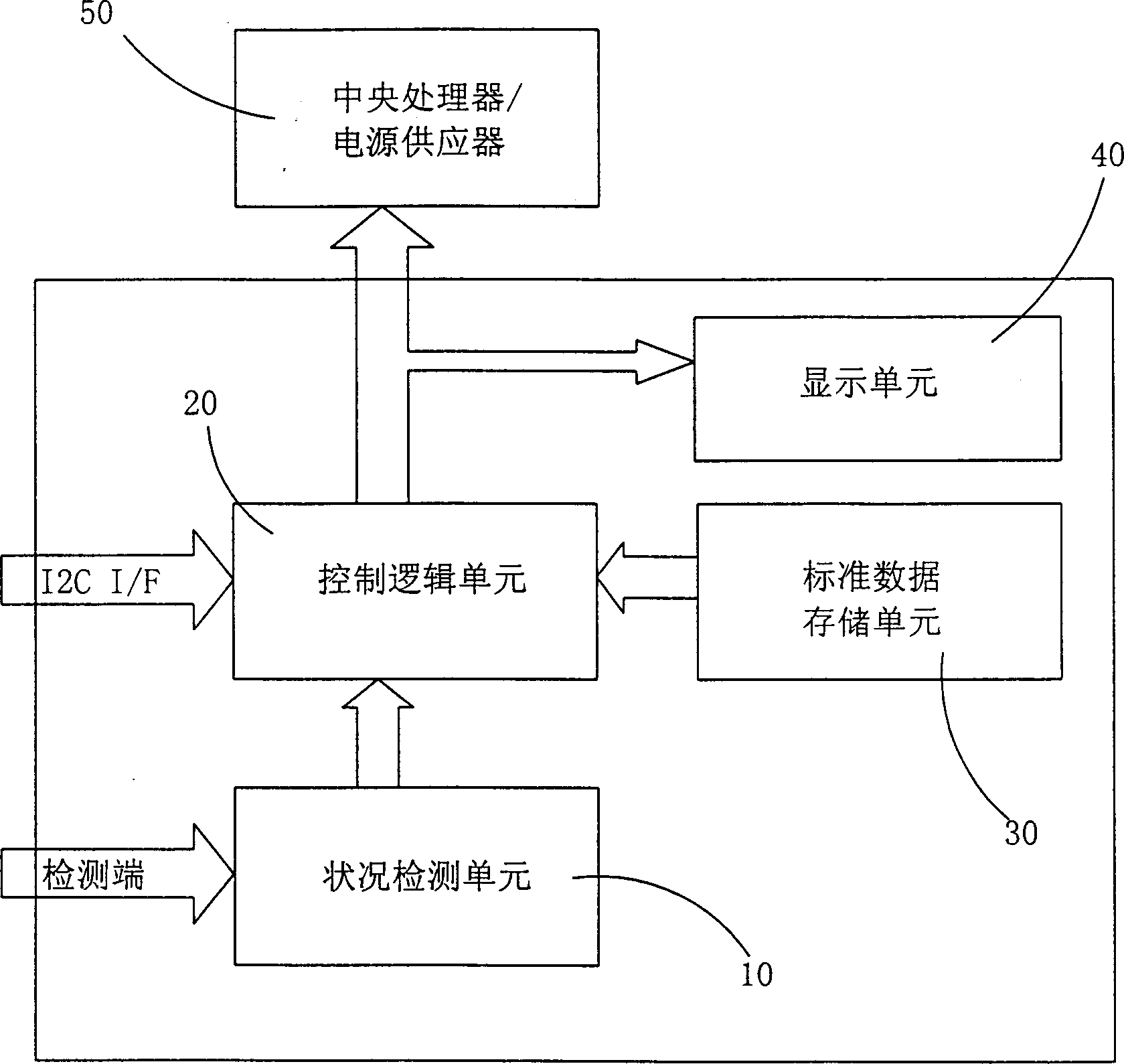
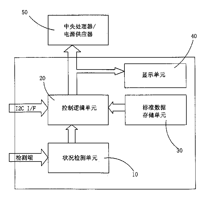
[0020] The present invention provides a system status display control module, such as figure 1 As shown, the module is installed on a computer and includes: a condition detection unit 10 , a control logic unit 20 , a standard data storage unit 30 , a display unit 40 , and a central processing unit / power supply 50 .

[0021] The module reads the real-time voltage, current, humidity of the central processing unit, the rotational speed of the fan and the temperature of the hard disk and other data of the internal parts of the computer, and then compares and displays the standard specification data of the internal parts of the computer, and then processes the data of the central processing unit. controller and power supply.

[0022] 1. The Status Detector 10, which...


PUM


Abstract

A system state displaying and controlling module for testing CPU, hard disk, heat-dispersing fan, etc. of computer is composed of a state detection unit for detecting the state of each unit and sending information to a control logic unit, the control logic unit comparing detected data with standard data for displaying result and controlling CPU/power supply and display, a standard data memory unit, and a display unit for displaying the compared result.

Description

technical field [0001] The invention relates to a system status display control module, in particular to a module for detecting, displaying and controlling the status of internal parts of a computer. Background technique [0002] The central processing unit (CPU) of today's personal computers, its manufacturing process has progressed from 3μM 20 years ago to 0.18μM today, and its speed has also increased from 4.77MHz of IBM PC / XT to 1.5GHz, so that the operating speed of the CPU continues to increase. However, although the operating speed has increased, the power consumption of the CPU has been continuously increased accordingly. Correspondingly, the CPU has generated higher and higher heat, so the cooling system and heat dissipation system of the CPU are more important in comparison. Otherwise, such a sophisticated CPU will be burned. [0003] The operating system and hardware of current personal computers have all done power management to the CPU, and the fans and radiato...

Claims


Application Information

Patent Timeline
IPC IPC(8): G06F1/18G06F1/20G06F11/30G06F11/32
CPCG06F1/181G06F1/206G06F11/3055G06F11/3058G06F11/328
Inventor 曲绍麟
Owner SOYO COMP
Why Eureka
Try Eureka