Wrist ring of wrist-type tonometer

The technology of a sphygmomanometer and a wrist cuff is applied in the structural field of a wrist cuff for a wrist-type sphygmomanometer, and can solve problems such as insufficient compression of the radial artery, insufficient compression of the ulnar artery, and insufficient width of the wrist cuff, etc.

Inactive Publication Date: 2002-12-11
OMRON HEALTHCARE CO LTD
View PDF0 Cites 11 Cited by
  • Summary
  • Abstract
  • Description
  • Claims
  • Application Information

AI Technical Summary

Problems solved by technology

However, due to the existence of the radius 2 and the flexor palmaris longus 4b, the expansion of the air bag 109 is hindered, and the radial artery 5 cannot be fully compressed, and, due to the existence of the flexor digitorum superficialis 6a and the ulnar root tendon 6b, it is hindered. The expansion of the air bag 109 cannot fully compress the ulnar artery 7
[0012] Originally, under the condition that the compression of the artery by the air bag 109 does not have any hindrance, if Figure 17 As shown in the schematic diagram of , by fully inflating the air bag 109, the prescribed wrist width W1 can be obtained. However, in the presence of the radius 2 and the flexor palmaris longus 4b, etc. Figure 18 As shown in the schematic diagram of , the expansion of the air bag 109 is hindered by the existence of the radius 2 and the flexor palmaris longus 4b, etc., so that the width W2 of the wristband is insufficient

Method used


Image

  • Wrist ring of wrist-type tonometer
  • Wrist ring of wrist-type tonometer
  • Wrist ring of wrist-type tonometer

Examples


Embodiment 1

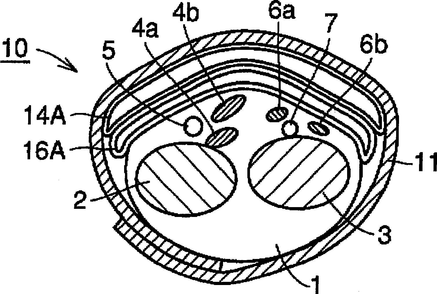
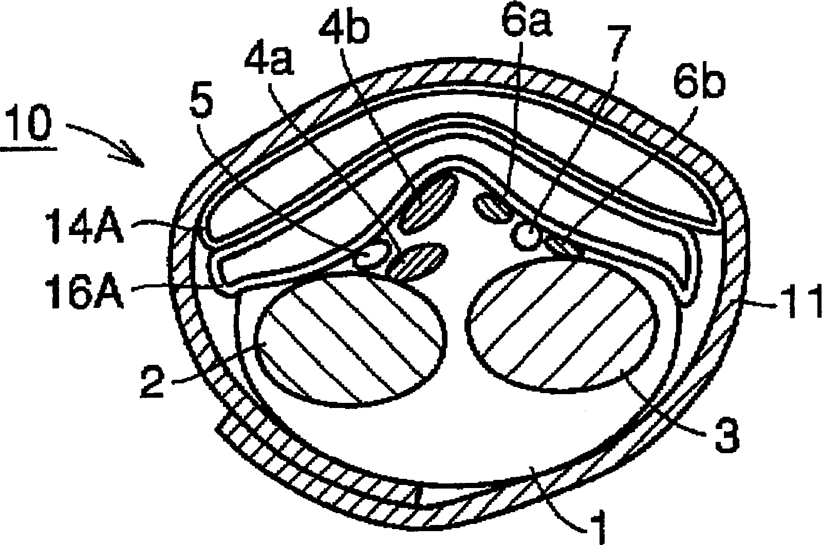
[0050] Below, refer to Figure 5 and Figure 6 The structure of Embodiment 1 based on the above-mentioned compression principle will be described. in addition, Figure 5 Only the air bag in the wrist cuff 10 for wrist sphygmomanometer is shown, showing the contracted state before supplying air, Figure 6 Indicates the state of expansion after air is supplied.

[0051] First, refer to Figure 5 , comprising: a first air bag 14B as a first inflation area, a second air bag as a second inflation area located between the first air bag 14B and the wrist and made of a material with higher stretchability than the first air bag 14B. Bag 16B. As a concrete material of the first air bag 14B, vinyl chloride (thickness of the film is about 0.3 mm) is used. Also, as another material used for the first air bag 14B, for example, EVA (vinyl acetate, film thickness of about 0.3 mm) or urethane (film thickness of about 0.3 mm) can be used.

[0052] And, in order to promote the expansion o...

Embodiment 2

[0057] Second, refer to Figure 7 and Figure 8 The structure of Embodiment 2 based on the above-mentioned compression principle will be described. and, Figure 7 It is a diagram showing only the air bag, showing the state before supplying air, Figure 8 Indicates the status of the air supply.

[0058] First, refer to Figure 7 , including: a first air bag 14C as a first inflation area, and a second air bag 14C as a second inflation area located between the first air bag 14C and the wrist and made of a material more stretchable than the first air bag 14C. Air bag 16C. The concrete material and the thickness of the film of the first air bag 14B are the same as those of the first embodiment above. In addition, the structure is also formed with gussets made of side walls 14a and 14b to promote expansion toward the wrist. The specific material of the second air bag 16C is also the same as that of the above-mentioned first embodiment. As a characteristic structure of the pre...


PUM

PropertyMeasurementUnit
Lengthaaaaaaaaaa
Widthaaaaaaaaaa
Heightaaaaaaaaaa

Abstract

A wrist cuff for a wrist-type sphygmomanometer, the wrist cuff (10) for a wrist-type sphygmomanometer comprising: a first air bag (14A) serving as a first expansion area, and a first air bag (14A) and a wrist Between, the second air bag (16A) as the second expansion area is made of a material with greater stretchability than the first air bag (14A). This wrist cuff for a wrist sphygmomanometer can reliably compress the arteries located in the wrist without being affected by the muscles, tendons and bones existing in the wrist.

Description

technical field [0001] The present invention relates to a wrist cuff for a sphygmomanometer used in a sphygmomanometer that is mounted on a living body to measure blood pressure, and more particularly to a wrist cuff for a wrist sphygmomanometer used to measure blood pressure on the wrist Meter the structure of the wristband. Background technique [0002] In recent years, more and more attention has been paid to self-management of blood pressure, and wrist-type sphygmomanometers, which can measure more conveniently than upper arms, are widely used in homes as home-use sphygmomanometers. Now refer to Figure 12 and Figure 13 The general structure of the conventional wrist-type blood pressure monitor 100 will be described. Figure 12 is an overall perspective view showing the appearance of the wrist blood pressure monitor 100, Figure 13 It is a block diagram showing the internal structure of the wrist blood pressure monitor 100 . Referring to these two drawings, a wrist b...

Claims


Application Information

Patent Timeline
IPC IPC(8): A61B5/022
CPCA61B5/02141A61B5/022A61B5/02233A61B5/681
Inventor 山越宪一奥正次郎田中孝英佐野佳彦加藤宏行
Owner OMRON HEALTHCARE CO LTD
Why Eureka
Try Eureka