Magnetic head

A magnetic head and magnet technology, applied to magnetic recording heads, manufacturing magnetic head surfaces, magnetic recording, etc., can solve problems such as easy wear of inspection surfaces, shortened life of magnetic heads 1, and wrinkling of banknotes 30

Inactive Publication Date: 2002-12-11
株式会社实值留场
View PDF0 Cites 3 Cited by
  • Summary
  • Abstract
  • Description
  • Claims
  • Application Information

AI Technical Summary

Problems solved by technology

Yet, when adopting this structure, because the banknote 30 that is squeezed on the inspection surface 3c of magnetic head 1 will slide on the inspection surf

Method used


Image

  • Magnetic head
  • Magnetic head
  • Magnetic head

Examples


Embodiment Construction

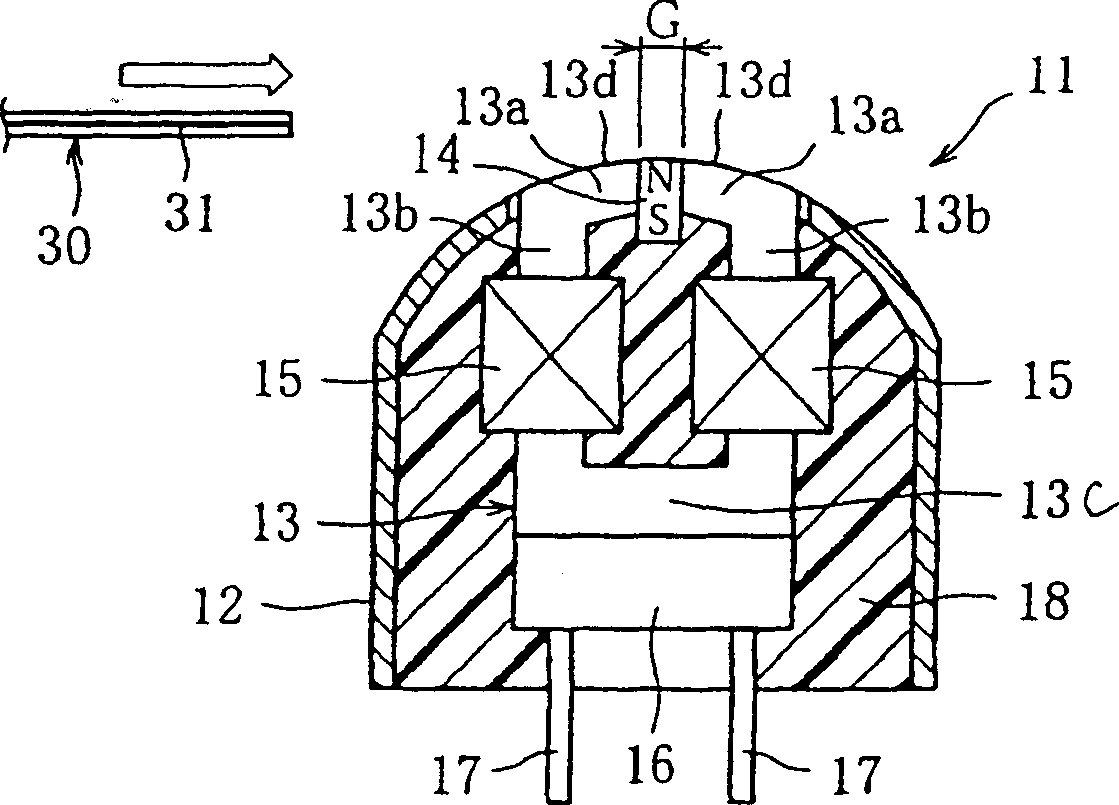
[0020] The following combination figure 1 A magnetic head according to a first embodiment of the present invention will be described.

[0021] The magnetic head 11 of this embodiment is provided as a recognition sensor, for example, in a banknote recognition device, and can detect the magnetic wire 31 in the banknote 30 which is an inspection object.

[0022] The magnetic head 11 is that the yoke 13, the magnet 14, the first and the second detection coils 15 and the supporting platform 16 are accommodated in the housing 12 together with the inner end portions of the first and the second connection terminals 17 and are molded with a resin 18. The outer end portions of the first and second connection terminals 17 are connected to an identification circuit portion (not shown) of the banknote identification device.

[0023] The yoke 13 consists of a central portion 13c extending in the width direction of the magnetic head fixed on the upper surface of the support table 16, first...


PUM


Abstract

A magnetic head (11), comprising: a yoke (13) forming a gap (G) at a top end (13a) constituting an inspection surface (13d), and a magnetic head ( 14), the coil (15) wound on the yoke. The magnetic head of the present invention can perform high-precision inspection without pressing the inspection object against the inspection surface.

Description

technical field [0001] The present invention relates to a magnetic head, and more particularly to a magnetic head capable of performing high-precision inspection without pressing an inspection object against an inspection surface. Background technique [0002] One type of banknote identification devices installed in automatic vending machines etc. uses a magnetic head to identify the authenticity of banknotes. for example, Figure 5 The magnetic head shown detects the magnetic wires inside the note. This magnetic head 1 has first and second yokes 3 fixed to a support base 6 , and a gap g is formed between tip ends 3 a of the two yokes 3 . Between the two yokes 3, a magnet 4 is fixed on the supporting table 6. The magnetic axis of the magnet 4 (the line connecting the N pole and the S pole) is set in the direction extending along the inspection surface 3c, and the N pole side and the S The end faces on the pole side are in contact with the base end portions 3 b of the first...

Claims


Application Information

Patent Timeline
IPC IPC(8): G07D7/04G01N27/72G01R33/038G06K7/08G07D7/00G11B5/127G11B5/17G11B5/187G11B5/23
CPCG11B5/1272G11B5/23G11B5/255
Inventor 右田实雄近森雅文
Owner 株式会社实值留场
Why Eureka
Try Eureka