Reflecting composite prism and optical pick-up with the prism

A compound prism and reflective technology, which is applied in the direction of integrated optical head device, beam guiding device, optical recording/reproduction, etc., can solve the problems of 5 large mirrors and difficulties in producing compact/thin optical pickup devices

Inactive Publication Date: 2002-12-11
SAMSUNG ELECTRONICS CO LTD
View PDF0 Cites 9 Cited by
  • Summary
  • Abstract
  • Description
  • Claims
  • Application Information

AI Technical Summary

Problems solved by technology

[0005] However, in the conventional optical pickup device having the above structure, in order to increase the size of the light beam input to the objective lens 3 to obtain a desired NA value, the mirror 5 must be made larger
Therefore, it is difficult to produce a compact / thin optical pickup device

Method used


Image

  • Reflecting composite prism and optical pick-up with the prism
  • Reflecting composite prism and optical pick-up with the prism
  • Reflecting composite prism and optical pick-up with the prism

Examples


Embodiment Construction

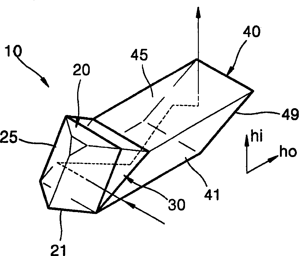
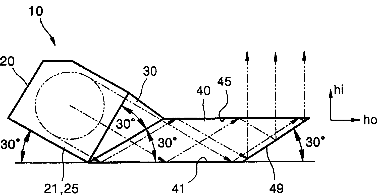
[0028] refer to figure 2 , the reflective composite prism 10 according to the present invention includes a first prism 20 and a second prism 40 . A light beam output from a light source (not shown) substantially parallel to the horizontal plane is input to the first prism 20, the light beam being perpendicular to the direction of the height hi of the optical system. The size of the light beam with respect to the height hi direction is reduced by utilizing the angle difference between the respective surfaces of the first prism 20 and the second prism 40 . Then, the light beam is reflected by the surface of the second prism 40 which forms an angle of less than 45° with respect to the horizontal plane, and is output in the height hi direction.

[0029] Here, considering an example in which the reflective compound prism 10 according to the present invention is used in an optical pickup device, the height hi direction of the optical system is assumed to indicate a direction along...


PUM

PropertyMeasurementUnit
refractive indexaaaaaaaaaa

Abstract

A reflective composite prism and a thin optical pickup device using the same. When the beam emitted from the light source passes through a reflective compound prism, the beam size is reduced in the height direction and then recovered when the beam is reflected by a surface at an angle of less than 45° to the horizontal, so that the beam size can be reduced without reducing the beam size. Reduce the height of the optical system. Therefore, when a reflective compound prism is used, a beam having a larger diameter incident on the reflective compound prism from a light source passes under the actuator at a height lower than the top of the beam diameter, and is picked up by the first prism of the second prism. Four reflective surfaces reflect, thereby restoring the original diameter of the beam. Therefore, a small and thin optical pickup device with a desired NA value is obtained.

Description

technical field [0001] The invention relates to a reflective composite prism capable of reducing the height of an optical system, and a thin optical pickup device using the prism. Background technique [0002] refer to figure 1 , the conventional optical pickup device has an optical system in which a light beam emitted from a light source (not shown) travels horizontally, is reflected by a reflector 5 having a reflective surface 5a with an inclination angle of 45°, travels in a height h direction, and The light is collected by the objective lens 3 to focus on the optical disc 1 . [0003] The recording density is determined by the size of the spot formed by the objective lens 3 on the recording surface of the optical disc 1 . As the wavelength of light used becomes shorter, the size of the light spot decreases, and the NA value (numerical aperture) of the objective lens 3 becomes larger. Assuming that the effective diameter and effective focal len...

Claims


Application Information

Patent Timeline
Patent Type & Authority Applications(China)
IPC IPC(8): G02B5/04G11B7/12G11B7/124G11B7/135G11B7/1356
CPCG02B5/04G11B7/12G11B7/124G11B7/1356
Inventor 金大式郑丞台延哲诚赵虔晧
Owner SAMSUNG ELECTRONICS CO LTD
Why Eureka
Try Eureka