Supercharge Your Innovation With Domain-Expert AI Agents!

Pin-grid array type socket

A grid array and pin technology, which is applied in the direction of component plug-in combination, coupling device, electrical equipment construction parts, etc.

Inactive Publication Date: 2002-12-18
JST MFG CO LTD
View PDF0 Cites 2 Cited by
  • Summary
  • Abstract
  • Description
  • Claims
  • Application Information

AI Technical Summary

Problems solved by technology

However, the unit price of the aforementioned conventional PGA socket 100 has not been reduced enough to meet demand

Method used


Image

  • Pin-grid array type socket
  • Pin-grid array type socket
  • Pin-grid array type socket

Examples


Embodiment Construction

[0015] DETAILED DESCRIPTION OF THE PREFERRED EMBODIMENTS Preferred embodiments of the present invention will be described below with reference to the accompanying drawings.

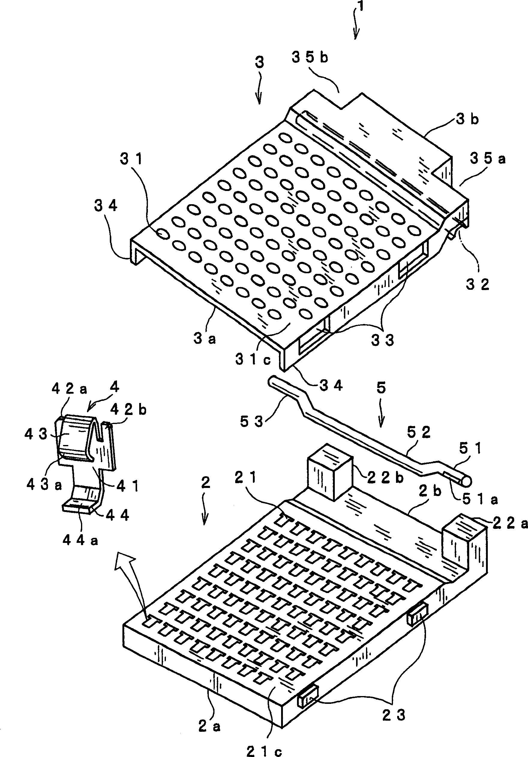
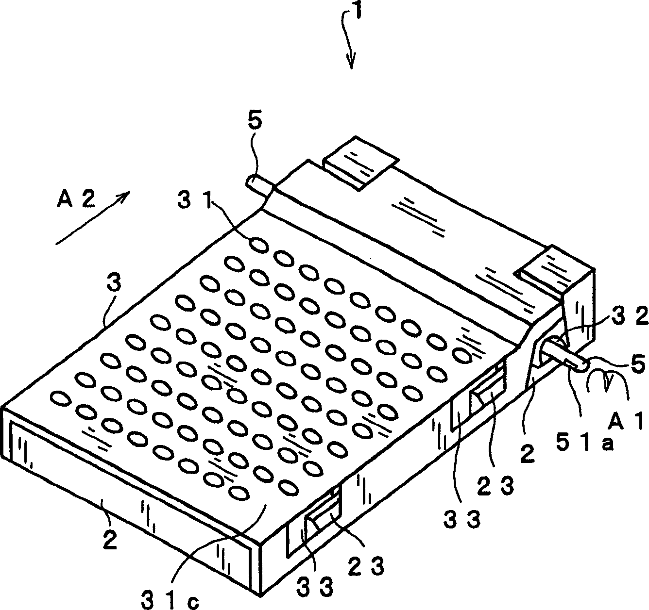
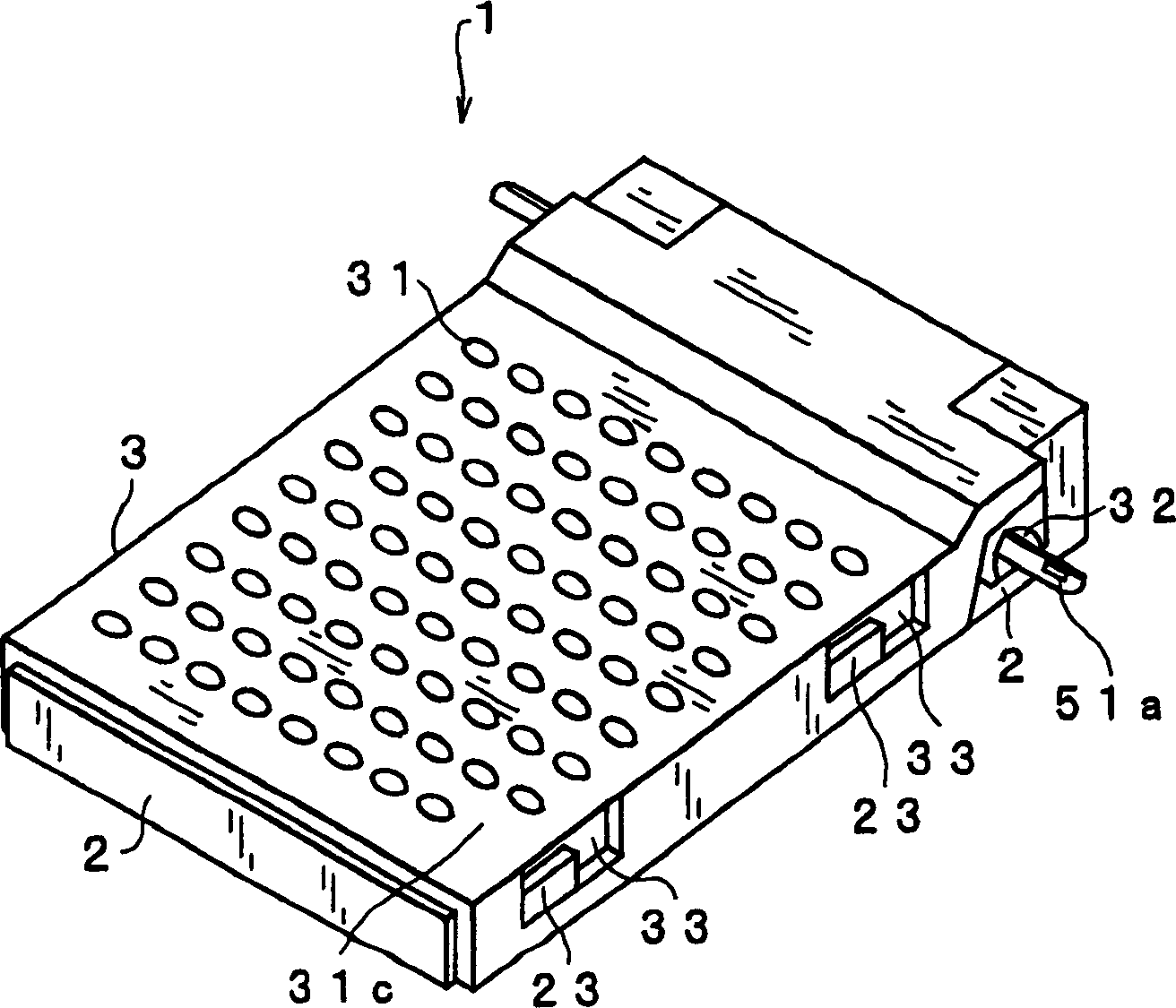
[0016] first refer to Figure 1-3 The structure of a PGA (Pin Grid Array) socket according to an embodiment of the present invention will be explained. figure 1 is an exploded perspective view showing a PGA (Pin Grid Array) socket. FIG. 2 is a perspective view showing such a PGA socket; (a) shows a state before sliding, and (b) shows a state after sliding. image 3 is a partial perspective view showing the base housing including the contacts.

[0017] figure 1 The PGA socket 1 shown in and 2 includes a base housing 2 ; a cover housing 3 positioned overlapping the base housing 2 ; a plurality of contacts 4 ; and an eccentric member 5 . The contacts 4 are made of conductive material. The base housing 2 and the cover housing 3 are made of non-conductive material.

[0018] A substantially plate-shaped...


PUM


Abstract

An eccentric member 5, which has a first shaft portion 51 and an eccentric portion 52, the first shaft portion is provided with a recess 51a, the central axis of the eccentric portion is different from the central axis of the first shaft portion 51, and the eccentric portion is at One end of the first shaft portion 51 is continuously formed. The concave portion 51 a has a concave surface whose boundary line divides the concave portion 51 a into a rectangular shape on the surface of the first shaft portion 51 . A flat-bladed screwdriver is engaged with the recess 51a and turned to slide the cover housing 3 over the base housing 2.

Description

technical field [0001] The invention relates to a PGA socket, which is used when a PGA (Pin Grid Array) plug-in with a plurality of pins arranged in a grid array is connected to a printed circuit board. Background technique [0002] For example, in a desktop computer, if a PGA plug-in that is provided with a plurality of pins in a grid array is to be connected to a printed circuit board such as a CPU (central processing unit), use such as Image 6 PGA socket 100 is shown. [0003] Image 6 The illustrated conventional PGA socket 100 includes a base housing 101 having contact holes (not shown) in a grid array; contacts (not shown) held in the contact holes of the base housing 101; A cover housing 102 that is provided with through holes 102a in a grid array, pins of the PGA card can be inserted from the through holes; slide. The L-shaped lever 103 includes a handle portion 103a which the operator can hold and turn in the vertical direction. When the lever 103 is rotated in ...

Claims


Application Information

Patent Timeline
Patent Type & Authority Applications(China)
IPC IPC(8): H01R33/76H01R13/193H05K7/10
CPCH05K7/1007H01R33/76H01R13/193
Inventor 田启明西田佳史
Owner JST MFG CO LTD
Features
  • R&D
  • Intellectual Property
  • Life Sciences
  • Materials
  • Tech Scout
  • Unparalleled Data Quality
  • Higher Quality Content
  • 60% Fewer Hallucinations
Learn More