
Fresnel lens

A technology of Fresnel lens and lens sheet, applied in lens, optics, instrument, etc., can solve problems such as poor self-support, difficulty in fixing, and increased cost

Inactive Publication Date: 2002-12-25
DAI NIPPON PRINTING CO LTD
View PDF0 Cites 2 Cited by
  • Summary
  • Abstract
  • Description
  • Claims
  • Application Information

AI Technical Summary

Problems solved by technology

[0008] However, for the existing Fresnel lens sheet, due to the thinning of the thickness, when it is used in a large screen, the self-supporting property is poor, and problems such as difficulty in fixing occur.
[0009] As a method of fixing a thin Fresnel lens sheet, there are measures such as applying tension to the Fresnel lens sheet, but corresponding parts are required, and in the case of a rear projection type screen, the area other than the image will increase. , but also increase the overall cost
[0010] In addition, the width of the fixed frame for fixing the Fresnel lens needs to be tens of mm, which will also cause problems

Method used


Image

  • Fresnel lens
  • Fresnel lens
  • Fresnel lens

Examples


no. 1 approach

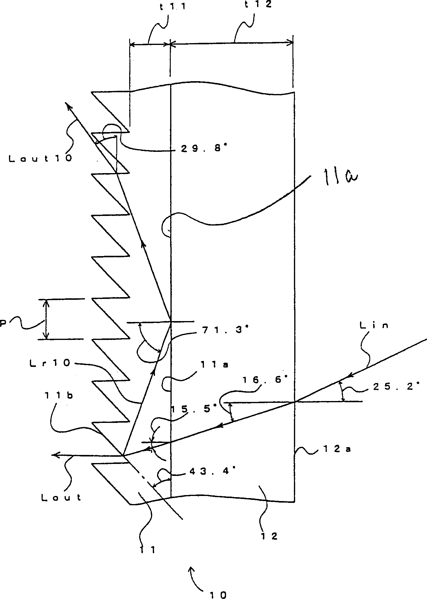
[0043] figure 1 It is a diagram explaining an example of the first embodiment of the Fresnel lens sheet according to the present invention.

[0044] In this embodiment, the Fresnel lens sheet 10 is provided with a lens layer 11 and a base material layer 12 , the diagonal size is 70 inches (aspect ratio is 4:3), and the focal length is 720 mm.

[0045] The lens layer 11 is a Fresnel lens shape with a pitch (pitch) P=0.1mm formed on the outgoing light side, a high refractive index layer with a refractive index n11=1.59, and a thickness t11=0.1mm from the bottom of the Fresnel lens . The lens layer 11 has a total reflection layer 11 a at the interface with the base material layer 12 .

[0046] The base material layer 12 is a parallel flat plate with a thickness t12 = 3 mm, and is a low refractive index layer made of acrylic resin with a refractive index n12 = 1.49. Also, in figure 1 In the figure, the plate thicknesses of the lens layer 11 and the base material layer 12, et...

no. 2 approach

[0069] Figure 6 It is a figure explaining an example of 2nd Embodiment of a Fresnel lens sheet in this invention.

[0070] In this embodiment, the Fresnel lens sheet 40 is a Fresnel lens sheet having a lens layer 41 and a base material layer 42, a diagonal size of 50 inches (aspect ratio of 4:3), and a focal length of 700 mm.

[0071] In this Fresnel lens sheet 40, on the optical axis of the Fresnel lens sheet 40, at a position of a projection distance of 700 mm, the image is vertically projected by a projector using a liquid crystal or a DLP (Digital Light Processor) or the like. Image light, together with scattering means (not shown), forms a transmission type projection screen.

[0072] The Fresnel lens sheet 40 has a total reflection surface 40 a formed at the interface between the lens layer 41 and the base material layer 42 .

[0073] The lens layer 41 is to form a Fresnel lens shape with a pitch (pitch) P=0.1mm on the outgoing light side, a high refractive index laye...


PUM

PropertyMeasurementUnit
Thicknessaaaaaaaaaa
Thicknessaaaaaaaaaa
Thicknessaaaaaaaaaa

Abstract

The invention discloses a Fresnel lens sheet used in a rear projection screen and a transmission projection screen using the Fresnel lens sheet. The Fresnel lens sheet is characterized in that it has at least a lens layer forming a Fresnel lens and a layered structure with a base material layer, and a total reflection surface is provided on the outgoing light side instead of the incident light side, and the lens is composed of When light is incident on either the side of the lens layer or the side of the base material layer, a part of the projected light transmitted from the lens layer to the base material layer is totally reflected. The effect is that regardless of the thickness of the lens layer, it is possible to obtain a Fresnel lens sheet that can reduce double images and can be easily fixed so that double images are not conspicuous.

Description

technical field [0001] The present invention relates to a Fresnel lens sheet used in a rear projection screen and a transmissive projection screen using the Fresnel lens sheet. Background technique [0002] The purpose of using such a Fresnel lens sheet and a transmissive projection screen is to generally deflect the projection light entering from the incident light plane and emit it at a desired angle from the exiting light plane. [0003] However, part of the projected light will be reflected on the outgoing light surface, so that the position of the outgoing light may be deflected from the original position of the outgoing light, that is, a double image is formed. [0004] Figure 11 , 12 It is a figure which shows the incident light ray in the conventional Fresnel lens sheet 100. [0005] Figure 11 Most of the incident light Lin incident on the Fresnel lens sheet 100 is emitted from the outgoing light surface 100 b to become regular outgoing light Lout. However, part...

Claims


Application Information

Patent Timeline
IPC IPC(8): G03B21/62
CPCG03B21/625
Inventor 关口博
Owner DAI NIPPON PRINTING CO LTD
Learn More