Plate thickness controller for continuous roll mill

A control device and a technology for a rolling mill, which are applied in the control device of a rolling mill, a driving device for a metal rolling mill, metal rolling, etc., and can solve the problems of insufficient plate thickness control accuracy and inability to achieve

Inactive Publication Date: 2003-01-22
MITSUBISHI ELECTRIC CORP
View PDF1 Cites 17 Cited by
  • Summary
  • Abstract
  • Description
  • Claims
  • Application Information

AI Technical Summary

Problems solved by technology

[0031] As mentioned above, the conventional continuous rolling mill plate thickness control device is required to set the control output on the basis of considering the adverse effect on the la

Method used


Image

  • Plate thickness controller for continuous roll mill
  • Plate thickness controller for continuous roll mill
  • Plate thickness controller for continuous roll mill

Examples


Embodiment Construction

[0047] Embodiment 1

[0048] Embodiment 1 of the present invention will be described in detail below with reference to the drawings.

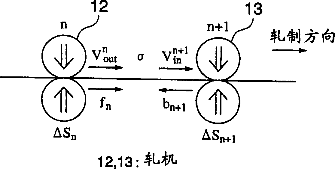
[0049] First refer to figure 1 The control principle of Embodiment 1 of the present invention will be described.

[0050] figure 1 Shown is a side view of the continuous rolling mill controlled by Embodiment 1 of the present invention, and the tension σ between the rolling mill 12 of stand number n and the rolling mill 13 of stand number n+1 is modeled and schematically expressed. A case where the tension σ of the material to be rolled is adjusted between the rolling mills 12 and 13 will be representatively described below.

[0051] exist figure 1 In the figure, the pressing direction (refer to the arrow) is the advancing direction of the material to be rolled, and the difference ΔS in the pressing position occurs due to the pressing load of each rolling mill 12 and 13 n , and ΔS n+1 .

[0052] In addition, the forward slip ratio fn i...


PUM


Abstract

To provide a plate thickness control system for a continuous rolling mill which improves accuracy on plate thickness control by formulating and regulating the influence which the correction amount of screw down position gives to the tensile force between rolling mills, and by making it easy to set up an output threshold value. This system comprises a measurement means to measure a plate speed variation Delta Vout at the exit of a rolling mill 12, a measurement means to measure a plate speed variation Delta Vin at the entrance of a rolling mill 13, a measurement means to measure a correction amount of screw down position Delta V Sn at the rolling mill 12 and the correction amount or screw down position Delta V Sn+1 at the rolling mill 13, a measured quantity calculation means 17 to calculate a measured quantity Pout ,n <(-)> , Pin ,n+1 <(+)> which affects accuracy on the plate width of the workpiece based on the plate speed variation Delta Vout , Delta Vin and the correction amount of screw down position Delta V Sn , Delta V Sn+1 , and a control output adjustment means 18 to adjust a plate control output during rolling the workpiece, using a measured quantity.

Description

technical field [0001] The present invention relates to a plate thickness control device for a continuous rolling mill that performs plate rolling, and in particular to a continuous rolling mill plate thickness control device that can adjust the control output in consideration of the influence of the quality imbalance of the control output on the lateral accuracy of the material to be rolled. Background technique [0002] Image 6 Shown is a block configuration diagram of a conventional continuous rolling mill thickness control device described in, for example, Japanese Patent Publication No. 6-71616, showing the most representative thickness control methods of the thickness gauge method and the An example of thickness control by monitoring method. [0003] exist Image 6 Among them, the rolling phenomenon in the rolling mill 2 controlled by the reduction device 1 is represented by calculation elements 3 and 8, and the thickness gauge type thickness control device and the mo...

Claims


Application Information

Patent Timeline
IPC IPC(8): B21B37/18B21B37/16
CPCB21B37/16B21B38/00B21B2275/04B21B2275/06
Inventor 井波治树
Owner MITSUBISHI ELECTRIC CORP
Why Eureka
Try Eureka