
Zero thread ring holder for chain type stitch sewing machine

A technology of holding device and chain stitch, which is applied in the sewing machine to cut off the thread mechanism, sewing machine components, sewing machine housing, etc., which can solve the problems of unstable continuous empty thread loop, low efficiency of sewing operation, and deterioration of fabric positioning and other problems, to achieve stable and continuous formation, good packing performance, and good packing performance

Inactive Publication Date: 2003-01-22
JUKI CORP
View PDF0 Cites 6 Cited by
  • Summary
  • Abstract
  • Description
  • Claims
  • Application Information

AI Technical Summary

Problems solved by technology

[0013] Therefore, when the cloth is loaded between the top of the needle plate 20 and the bottom of the presser foot 10B, the cloth will be blocked by the front end of the empty loop presser foot 10G protruding from the bottom of the presser foot 10B, so that the positioning of the cloth will deteriorate. Creates a problem of inefficiency in sewing operations, especially when thick cloth is put in
[0014] In addition, the holding force for pressing and holding the empty thread loop on the top of the needle plate 20 with the empty thread loop presser foot 10G is determined by the elastic force of the spring 10I. If the elastic force of the spring 10I is weak for the empty thread loop Otherwise, the empty thread loop will be pulled in the direction opposite to the cloth feeding direction due to the tightness of the upper thread, and the empty thread loop cannot be formed stably and continuously.
[0015] In addition, when there is a height difference between the bottom of the empty thread loop presser 10G and the bottom of the presser foot 10B, the empty thread loop cannot be kept between the bottom of the empty thread loop presser part and the top of the needle plate.

Method used


Image

  • Zero thread ring holder for chain type stitch sewing machine
  • Zero thread ring holder for chain type stitch sewing machine
  • Zero thread ring holder for chain type stitch sewing machine

Examples


Embodiment Construction

[0033] Refer to the following Figure 1 to Figure 6 Examples of the present invention will be described.

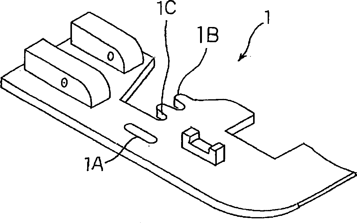
[0034] figure 1 It is a perspective view of the presser foot 1, which has a long needle hole 1A along the cloth feeding direction and a needle hole 1C with two sliding thread pieces 1B as well known.

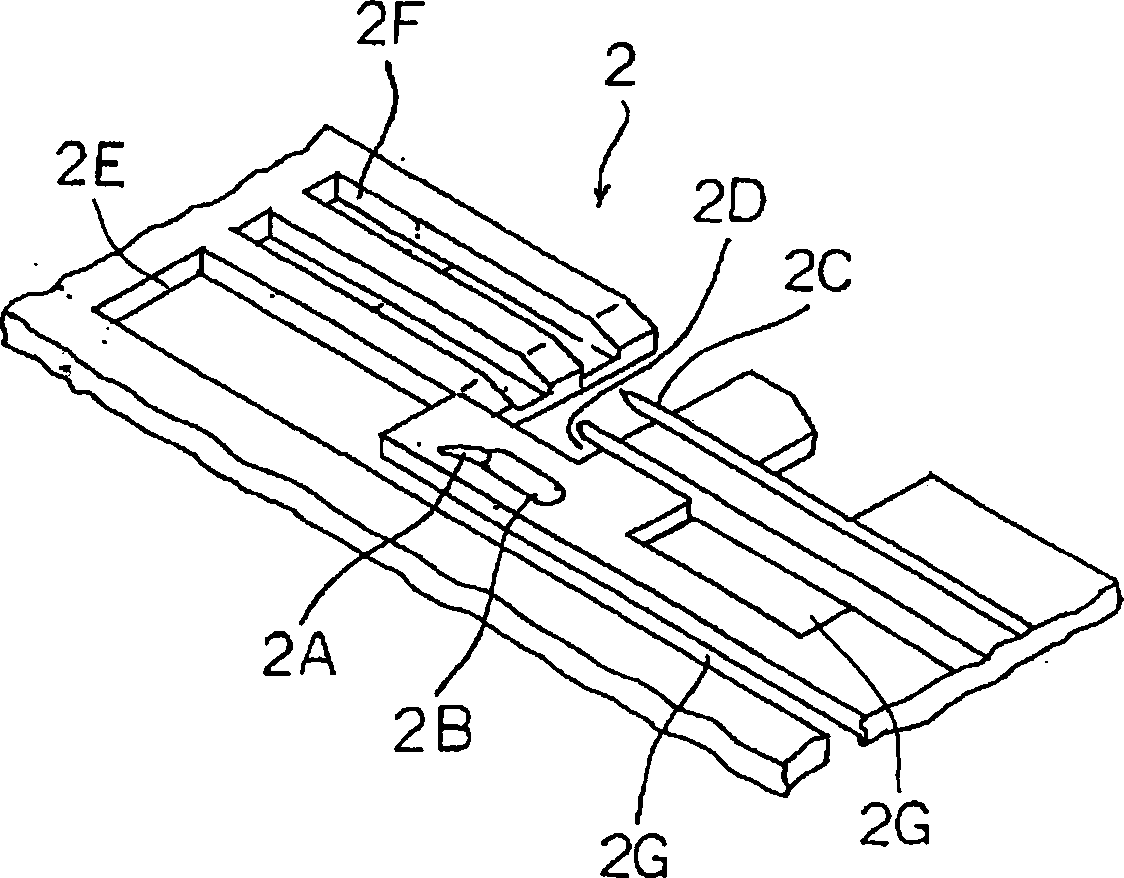
[0035] figure 2 is a perspective view of the needle plate 2 on which the corresponding figure 1 The needle hole 1A is formed with a needle hole 2B whose length is along the cloth feeding direction and has an empty thread loop guide groove 2A in front of the cloth feeding direction.

[0036] In addition, on this needle plate 2, two thread slide pieces 2C and needle holes 2D corresponding to the two thread slide pieces 1B of the above-mentioned presser foot 1 are formed, and a needle hole 2C located in the needle hole 2C forming the empty thread loop guide groove 2A is formed. The wide main feed hole 2E in front of the feed direction and the narrow main feed hole 2F in...


PUM


Abstract

An empty chain locking member is mounted on a chain stitch sewing machine comprising a needle for penetrating through a cloth on a throat plate to be vertically moved interlockingly with a main spindle of the sewing machine, thereby holding a needle thread, a cloth presser mounted on the throat plate and serving to press the cloth, a looper having a looper thread for reciprocating in such a direction as to cross a cloth feeding direction below the throat plate interlockingly with the main spindle of the sewing machine, a main feed dog for feeding a loop formed by the needle thread and the looper thread in cooperation of the needle and the looper rearward in the cloth feeding direction, and a loop engagement member for protruding from an upper surface of the throat plate and engaging the loop with the cloth presser when the main feed dog is descending from the upper surface of the throat plate. The present invention aims to facilitating setting of cloth between a cloth presser and a throat plate and to surely form an empty chain.

Description

technical field [0001] The invention relates to an empty thread loop holding device of a chain stitch sewing machine, in particular to an empty thread loop stopping device of a sewing machine which continuously forms chain stitches by upper thread and bottom thread. Background technique [0002] Such as Figure 7 , Figure 8 Empty thread loop retaining devices for sewing machines of the type shown are well known. [0003] This well-known chain stitch sewing machine is a chain stitch sewing machine that can form both chain stitch overlock and wide lockstitch stitches [0004] Figure 7 It is a side view of the presser foot device 10, and it is comprised as follows: 10A is a support body which can be attached and detached flexibly to the presser foot bar which is not shown in figure. 10B is a presser foot, and its horizontal shaft 10C can be attached to and detached from the lower end of the supporting body 10A by a lever 10D. 10E is a spring, the base of which is supported...

Claims


Application Information

Patent Timeline
Patent Type & Authority Applications(China)
IPC IPC(8): D05B65/06D05B1/10D05B27/02D05B29/06D05B73/12
CPCD05B73/12D05B1/10D05B27/02D05B29/06
Inventor 贞末数也西村悟
Owner JUKI CORP
Learn More