
Field furrower adopting cone disk clutch

A clutch and ditching machine technology, applied in the field of machinery, can solve the problems of compact structure, increased operating force, and small friction area, which is not as good as the multi-plate type, so as to prevent accidents caused by the rotation of the cutter head, reduce the radial size, good separation effect

Inactive Publication Date: 2003-02-05
葛玉明
View PDF0 Cites 0 Cited by
  • Summary
  • Abstract
  • Description
  • Claims
  • Application Information

AI Technical Summary

Problems solved by technology

The existing cone-disc clutch does have some shortcomings: 1. The structure of the traditional cone-disc clutch is not as compact as the multi-plate type, because the friction area is small, the friction force is small, and the torque that can be transmitted is small. If the pressure of the spring is appropriately increased , the friction force can be increased to increase the torque, but the operating force will also increase accordingly, to the point that it cannot be operated, that is, the operating force to separate the cone-disc will become larger, and the operator will be very laborious to pull it by hand.
Its structure is not compact enough
2. The driving disk and driven disk of the traditional cone-disc clutch are installed on two shafts respectively, which is another reason why the structure is not compact enough
However, the traditional flat disc friction clutch also has many shortcomings: 1. The separation effect is poor, and even the separation is unclear
This phenomenon will bring great potential safety hazards, because: there are many cutting knives on the cutter head, and when the ditching machine stops ditching and turning at the head of the field or driving on the road, the high-speed rotating cutter head will hurt the operator and pedestrians. bring great danger
This problem has become a major difficulty in the design of trenchers, and it has existed for many years but cannot be solved
2. The structure of the traditional flat plate clutch is complex and heavy
3. Due to the complex structure, it is difficult to maintain, replace parts and debug, and can only be repaired and debugged by skilled workers who have received professional training
The space between the driven plate and the active plate is very small, and the adjustment distance between the three release levers and the release bearing has a tolerance of 0.3 mm, which cannot be adjusted accurately by unskilled operators; if the adjustment is not correct, insufficient bonding force will occur and the friction surface will be burned Or the problem of obvious separation; the users of the ditching machine are farmers and mechanics, and it is generally difficult to master its maintenance and debugging technology, which causes inconvenience in use
4. Due to the complex structure, its manufacturing cost is relatively high
5. The operating parts are easily damaged
When separating, the separation claws and separation bearings are under great pressure, and they are in high-speed operation, the friction is very serious, and the separation bearings are often damaged. As an agricultural machine, the trencher has poor working conditions, and it has more contact The muddy water, dust and sundries in the environment make the problem of clutch disengagement more serious

Method used


Image

  • Field furrower adopting cone disk clutch
  • Field furrower adopting cone disk clutch
  • Field furrower adopting cone disk clutch

Examples


Embodiment 1

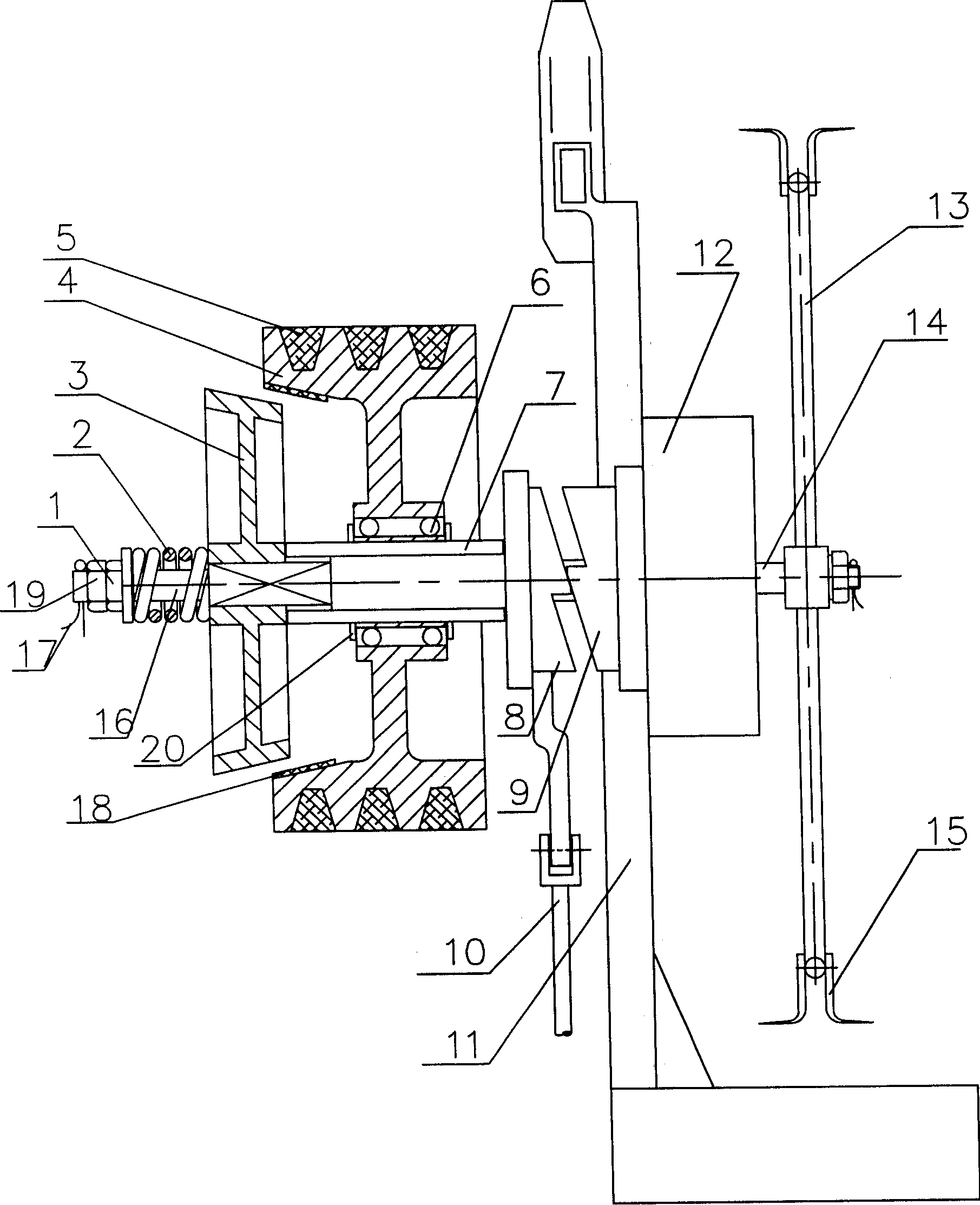
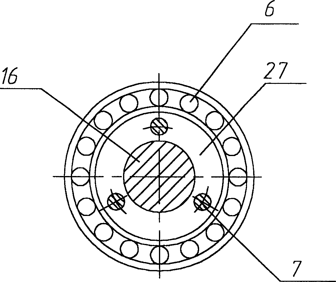
[0010] Embodiment 1, a farmland ditching machine using a cone-disk clutch, including a gearbox, a cutter head, a transmission device and a clutch that drive the cutter head to rotate, which are arranged on the frame. Its characteristics are: the clutch adopts a cone-disc clutch, and the structure of the clutch refers to figure 1: The clutch is disengaged. The clutch part in the figure has been cut horizontally, 16 is the driven shaft, the driven disc 3 is connected with the driven shaft 16 through a spline, the driven disc 3 can move in series on the driven shaft 16, but cannot rotate freely; The disc 4 is fixed to the driven shaft 16 through the bearing 6. There are retaining rings on both sides of the bearing 6 to limit the displacement of the bearing 6. The driving disc 4 can rotate freely on the driven shaft 16. The driving disc 4 is passed through a flexible transmission device such as a chain or a triangle. Driven by the belt 5; the separation claw 8 is set on the drive...

Embodiment 2

[0011] Embodiment 2, with reference to figure 2 A special cover is set on the driven shaft 16, and a through hole is punched in the axial direction of the cover, as the passage of the push rod 9 is set. The inner ring of the bearing is fixedly connected to the special sleeve.

Embodiment 3

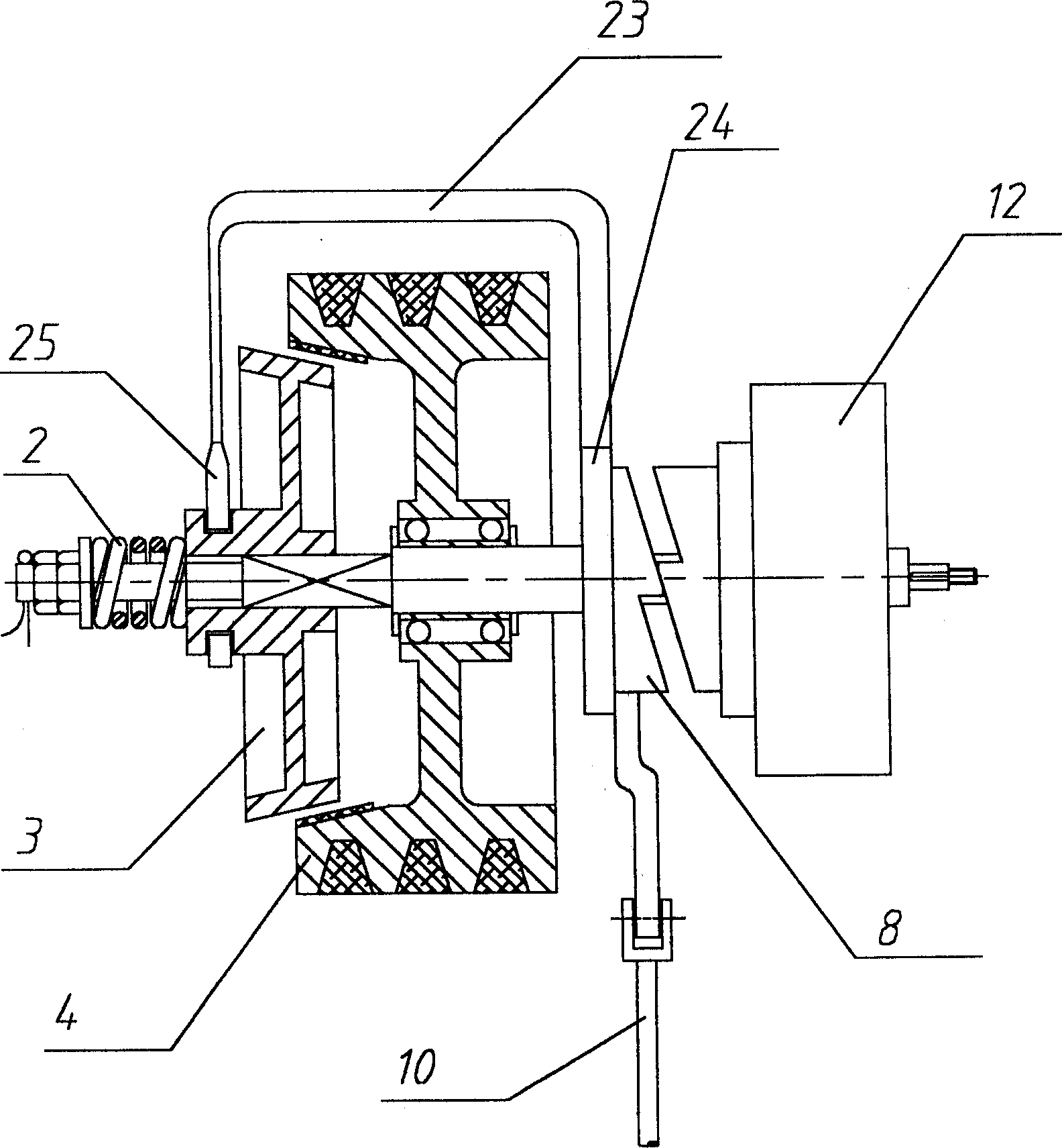
[0012] Embodiment 3, with reference to image 3 : The clutch is disengaged. There is a collar at both ends of a bow-shaped push rod, one end is set on the separation claw, and the other end is set in the control groove of the driven disc; when the separation claw is pulled, the bow-shaped push rod will be driven by the screw force. Push the driving disc outward, and the clutch will disengage; on the contrary, loosen the separation claw, the separation claw will no longer exert force on the bow push rod, and will move freely to the side of the box under the action of the spring force outside the driven disc. The driven disc is pressed tightly into the driving disc, and the clutch is engaged.


PUM


Abstract

The furrower includes speed reducer box mounted on the machine frame, colter disk, driving device for driving colter disk shaft and making it rotate and clutch, and is characterized by that it adopts cone disk clutch, on the cone disk clutch shaft a conical driving disk and a driven disk are mounted, both are tightly compressed together by spring, at the same time it adopts screw clutch as control mechanism, one end of the driven shaft is equipped with disengaging pawl, on the shaft an axial channel is set, in the channel a pin-lift is set, and one end of the pin-lift is placed against disengaging pawl, and its another end is planced against driven disk. Its structure is more simple and compact.

Description

technical field [0001] The invention belongs to the field of machinery and relates to a farmland ditching machine using a cone-disc clutch. Background technique [0002] With the development of agricultural mechanization, all kinds of agricultural machinery have also developed more and more complete, among which the farmland ditching machine has also developed rapidly, and large-scale rear-mounted ditching machines and small front-mounted ditching machines have appeared. The various components of various trenchers, such as cutterheads, blades, depth stops, etc., are also being continuously improved. Its structure basically includes a box set on the frame, a cutter head, a transmission device and a clutch that drive the cutter head to rotate. The used clutches of ditching machines in the prior art mainly contain jaw clutches and flat disc friction clutches, especially multi-plate flat disc friction clutches; and conical friction clutches (hereinafter referred to as cone disc...

Claims


Application Information

Patent Timeline
Patent Type & Authority Applications(China)
IPC IPC(8): A01B13/16A01B71/00
Inventor 葛玉明葛伟岸葛桂萍
Owner 葛玉明
Learn More