Band bundling machine

A technology of a strapping machine and a strapping belt, which is applied in the field of strapping machines, can solve the problems of difficulty in placing the objects to be bundled, reduction in the efficiency of the strapping work, and the like.

Inactive Publication Date: 2003-02-12
畑谷宽
View PDF0 Cites 16 Cited by
  • Summary
  • Abstract
  • Description
  • Claims
  • Application Information

AI Technical Summary

Problems solved by technology

Once the belt loop is deformed, it will be difficult to place the bundled object in the belt loop
[0006] As a result, the user must pick up the top of the belt loop by hand in order to place the bundled object in the belt loop, which greatly reduces the efficiency of the binding work.

Method used


Image

  • Band bundling machine
  • Band bundling machine
  • Band bundling machine

Examples


Embodiment Construction

[0014] Preferred embodiments of the present invention are described with reference to the drawings.

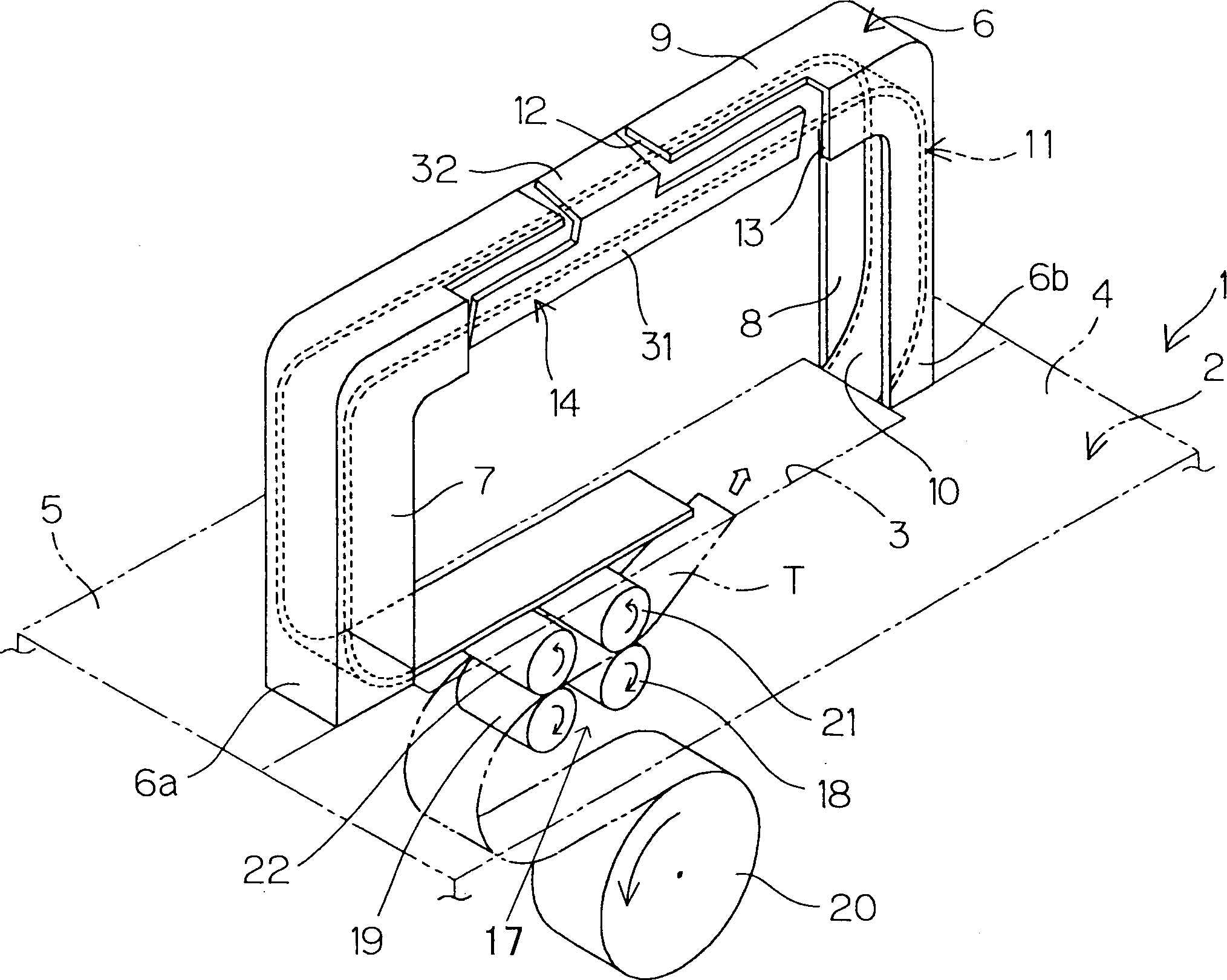
[0015] figure 1 The main part of the strapping machine which is one embodiment of this invention is shown. Referring to this figure, the top of the strapping machine main body 1 is formed by a workbench 2 for placing objects to be bundled. This workbench 2 is divided into a front workbench 4 and a rear workbench 5 with a passing groove 3 serving as a passage for the binding band interposed therebetween. At both ends of the passing groove 3 and above the table 2, leg portions 6a, 6b on which an arched guide frame 6 is arranged are fixed. The guide frame 6 is formed in a shape having a pair of flanges 7, 8 and a web 9 connecting the flanges 7, 8 with a U-shaped cross section (so-called groove shape). The front side wall and the rear side wall of the guide channel 10 are formed by the above pair of flanges 7 and 8 .

[0016] In addition, inside the guide frame 6, a guide memb...


PUM


Abstract

A binding machine with a tape comprises a table (2) for putting a material (A) to be bound, a tape passage groove (3) formed on the table (2), and a guiding member (11) in an arch shape provided above the tape passage groove (3). A loop (L) formed by a tape (T) of a predetermined size is formed along the guiding member (11). There is provided a tape receiving member (14) which can be displaced to first and second positions. At least a part of the tape receiving member (14) at the first position advances into the loop (L), to prevent the top of the loop (L) from hanging.

Description

technical field [0001] The present invention relates to a belt type binding machine (comprising) which forms a belt loop from a binding belt and tightens the belt loop to bind objects to be bound. Background technique [0002] As a small-sized binding machine for binding banknotes in the past, there is provided at least one side of which is wrapped with a thermally adhesive binding tape to wrap the bound object, and at the same time make the outer surface of the winding start part overlap with the inner surface of the winding end part, and after overlapping A strapping machine that binds the object to be bundled by applying pressure to the heating and pressing part heated by a heater, and thermally welding the strapping tape coated with thermoplastic resin. [0003] This kind of strapping machine forms a small strap loop at the end of the strap drawn out from the strapping roller held in the device in a freely rotatable manner. By feeding the strapping strap from the strappi...

Claims


Application Information

Patent Timeline
Patent Type & Authority Applications(China)
IPC IPC(8): B65B13/02B65B13/06B65B13/18
CPCB65B13/06Y10S412/902B65B13/18B65B13/02
Inventor 畑谷宽
Owner 畑谷宽
Why Eureka
Try Eureka