Check patentability & draft patents in minutes with Patsnap Eureka AI!

Compound switch set for vehicle

A composite switch and switch group technology, applied in the direction of electric switches, vehicle components, electrical components, etc., can solve the problems of time-consuming assembly and lack of reliability of electrical connections

Inactive Publication Date: 2003-03-12
ALPS ALPINE CO LTD
View PDF0 Cites 1 Cited by
  • Summary
  • Abstract
  • Description
  • Claims
  • Application Information

AI Technical Summary

Problems solved by technology

In such a conventional technology, it is necessary to prepare a plurality of printed circuit boards, which not only takes time for assembly, but also has the problem of lack of reliability of electrical connection because terminals are used to connect the switches of each seat and the printed circuit board for transmission.

Method used


Image

  • Compound switch set for vehicle
  • Compound switch set for vehicle
  • Compound switch set for vehicle

Examples


Embodiment Construction

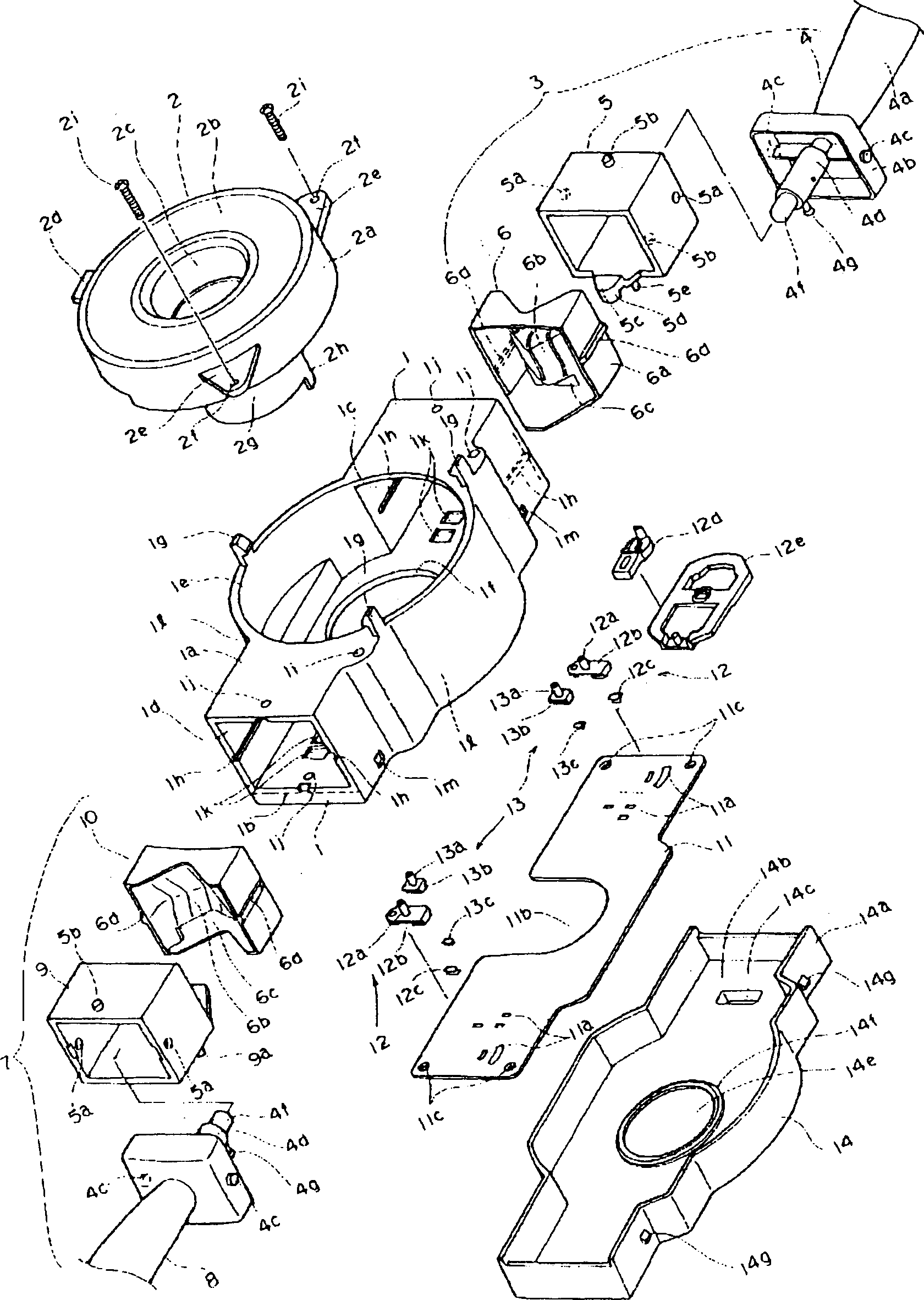
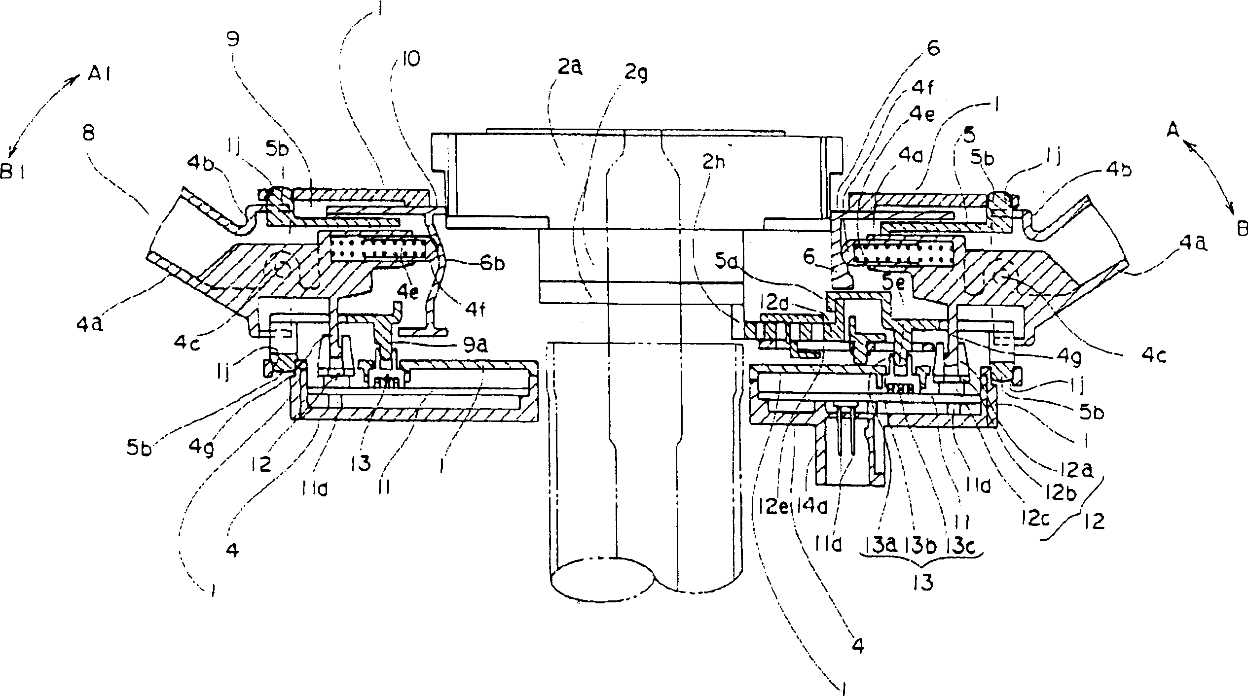
[0044] Utilize figure to illustrate the embodiment of composite switch group for vehicle of the present invention, figure represents respectively: figure 1 It is an exploded perspective view of an embodiment of the composite switch group for vehicles of the present invention, figure 2 It is a cross-sectional view of the main part of the vehicle composite switch group embodiment of the present invention, image 3 It is a longitudinal sectional view of the main part of the embodiment of the compound switch group for vehicles of the present invention.

[0045] Next, combine Figure 1 ~ Figure 3 The structure of the composite switch group for vehicles of the present invention will be described.

[0046] hood 1, such as figure 1 As shown, it is in the shape of a long box made of insulating resin. There is a rectangular opening 1c at one end in the longitudinal direction, and a rectangular opening 1d at the other end in the longitudinal direction. The left and right walls of t...


PUM


Abstract

A plurality of switchable contacts are provided on a relaying printed circuit board for centralized relaying of signals between a vehicle per se and a switch unit; a plurality of contact change-over members for connecting and disconnecting the switchable contacts are mounted on this printed circuit board; a drive member oscillatable from outside to inside of a box-shaped housing is fitted to each end of the housing in a lengthwise direction; the printed circuit board is fixed to an outer part of an under face of the housing to cause the contact change-over members to face the inside of the housing; the drive members and the contact change-over members are engaged with each other to oscillate the drive members; and the switchable contacts on the printed circuit board are thereby changed over. Therefore, a vehicular compound switch unit is obtained which is reduced in the number of used printed circuit boards, excellent in assemblability and enhanced in reliability for electrical connection.

Description

technical field [0001] The invention relates to a composite switch group for switching various functions of the vehicle, especially a composite switch group located around the steering wheel of the vehicle. Background technique [0002] Drawings of a conventional composite switch group for vehicles are described below. Figure 4 It is an exploded perspective view showing the outline of a conventional composite switch unit for vehicles, Figure 5 It is a schematic cross-sectional view of the main part of the conventional composite switch group for vehicles, and FIG. 6 is a longitudinal cross-sectional view of the main part of one side of the conventional composite switch group for vehicles, Figure 7 It is a cross-sectional view of the main part of one side of the main part of the conventional composite switch group for vehicles shown in FIG. 6 . [0003] The following describes the structure of the conventional composite switch group for vehicles, such as Figure 4 and Fi...

Claims


Application Information

Patent Timeline
Patent Type & Authority Applications(China)
IPC IPC(8): B60R16/02B60Q1/14H01H9/00H01H25/00H01H25/04
CPCB60Q1/1461H01H9/00
Inventor 高桥淳夫伊藤刚彦
Owner ALPS ALPINE CO LTD
Features
  • R&D
  • Intellectual Property
  • Life Sciences
  • Materials
  • Tech Scout
  • Unparalleled Data Quality
  • Higher Quality Content
  • 60% Fewer Hallucinations
Learn More