Mounting structure of fuel box for motor bicycle

A technology for motorized two-wheeled vehicles and fuel tanks, which is applied in the direction of machines/engines, liquid fuel feeders, and charging systems, and can solve the problems of not being able to use and not being able to use rotating support structures

Inactive Publication Date: 2003-03-19
HONDA MOTOR CO LTD
View PDF0 Cites 5 Cited by
  • Summary
  • Abstract
  • Description
  • Claims
  • Application Information

AI Technical Summary

Problems solved by technology

However, one end of the fuel tank must be fixed with a locking mechanism. Although the above-mentioned original combination structure is simple and conveni

Method used


Image

  • Mounting structure of fuel box for motor bicycle
  • Mounting structure of fuel box for motor bicycle
  • Mounting structure of fuel box for motor bicycle

Examples


Embodiment Construction

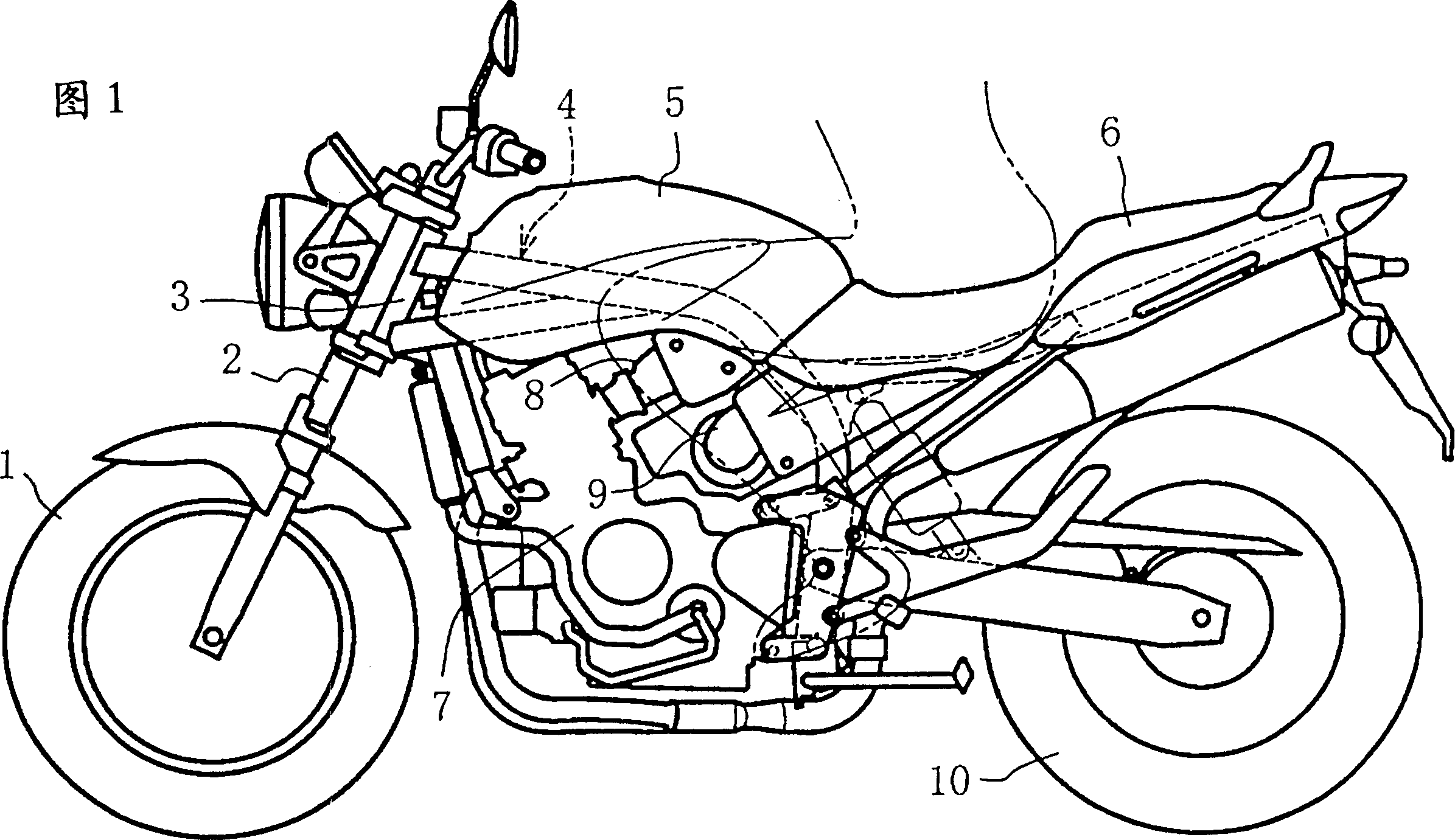
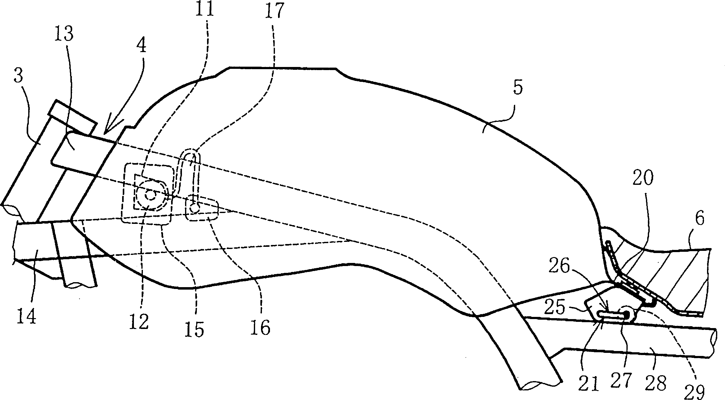
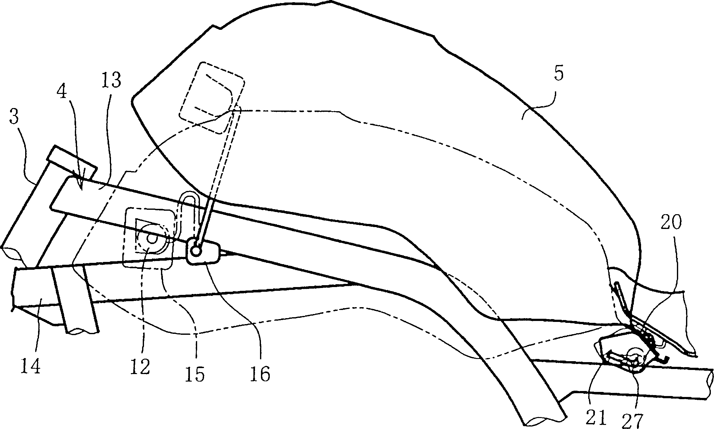
[0018] An embodiment is described below according to the accompanying drawings. Fig. 1 is a side view of a motorcycle to which this embodiment is applied, figure 2 is the side view of the fuel tank, image 3 It is a figure showing the state when the fuel tank turns, Figure 4 is the enlarged side view of the hinge, Figure 5 yes Figure 4 The 5-5 line sectional view, Image 6 is a cutaway view of the front of the fuel tank, Figure 7 It is an explanatory diagram of the operation of the hinge.

[0019] First of all, in Figure 1, the symbol 1 is the front wheel, 2 is the front fork, 3 is the head pipe, 4 is the single-cone body frame, 5 is the fuel tank, 6 is the seat, 7 is the engine, 8 Is the throttle body of the fuel injection device, 9 is the air filter, 10 is the rear wheel.

[0020] Such as figure 2 with image 3 As shown, the fuel tank 5 is equipped with a substantially U-shaped coupling member 11 opened forward on the side of the front end, and is freely disenga...


PUM


Abstract

When a fuel tank is supported rotatably, one end side of the fuel tank must be fixed by a lock mechanism. Although the background art engaging structure is simple and convenient, when the lock mechanism cannot be provided due to space limitations, a rotating support structure cannot be employed. An engaging member is provided on the front portion of the fuel tank and is inserted from the rear side to be engaged with a retaining member and to be pulled rearwardly for disengagement. A fuel tank is provided at a rear end thereof with a hinge. A bolt relatively moving in a guide groove formed in a side plate of the hinge is supported on a collar fixed to a seat rail. The hinge is slideable and rotatable.

Description

【Technical field】 [0001] The present invention relates to a mounting structure for fuel for motorcycles, and more particularly to a mounting structure in which a fuel tank is freely rotatable. 【technical background】 [0002] As the installation structure of the fuel tank, it is well known to provide a substantially U-shaped connecting member open to the front at the front of the fuel tank, and to connect the connecting member by inserting the connecting member into the locking member on the side of the vehicle body frame. The rear end of the fuel tank is provided with a mounting plate that protrudes from the bottom of the seat. By fixing the plate on the car body frame with bolts, the fuel tank can be installed on the car body frame at the front and rear. . [0003] In addition, a structure that supports the fuel tank freely in rotation is known. In this case, one end of the fuel tank is mounted on the vehicle body frame by a hinge, and a locking mechanism or the like is pr...

Claims


Application Information

Patent Timeline
IPC IPC(8): B62J35/00F02M37/00
CPCB62J35/00
Inventor 福永博文筒井则吉
Owner HONDA MOTOR CO LTD
Why Eureka
Try Eureka