Surface treatment apparatus

A surface treatment device and surface treatment technology, which are used in devices for applying liquid to surfaces, pretreatment surfaces, coatings, etc., can solve the problems of deterioration of the operating environment, excess etching, human danger, etc., to maintain the operating environment and work. The effect of environmental improvement and good working environment

Inactive Publication Date: 2003-03-19
ALMEX PE INC
View PDF0 Cites 2 Cited by
  • Summary
  • Abstract
  • Description
  • Claims
  • Application Information

AI Technical Summary

Problems solved by technology

However, due to many reasons such as technology, equipment cost, layout, etc., there is a limit to shortening the time for sending up in the direction of U1, horizontally in the direction of H2, and down in the direction of D2.
[0009] In this way, when the first surface treatment is, for example, etching treatment, and the second surface treatment is, for example, water washing treatment, the time left in the air from the end of the first surface treatment process to the start of the second surface treatment process If the time is longer than necessary, since the reaction speed of the chemical solution is fast, the etching treatment solution adhered to or remains on the surface of the workpiece W will cause excessive etching, scratches, and oxide film formation (quality deterioration).
In other words, the quality cannot be further improved
[0010] Moreover, since the adhered and remaining first treatment liquid splashes from the workpiece W during the horizontal conveyance in the H2 direction, it may pollute the surrounding environment and cause danger to people due to the liquid properties.
In addition, due to the difference in the composition of the first treatment liquid, a large amount of gas or mist is generated from the first surface treatment tank whose upper part is open, so the operating environment is deteriorated and improvement is required.

Method used


Image

  • Surface treatment apparatus
  • Surface treatment apparatus
  • Surface treatment apparatus

Examples


Embodiment Construction

[0029] Hereinafter, embodiments of the present invention will be described in detail with reference to the drawings.

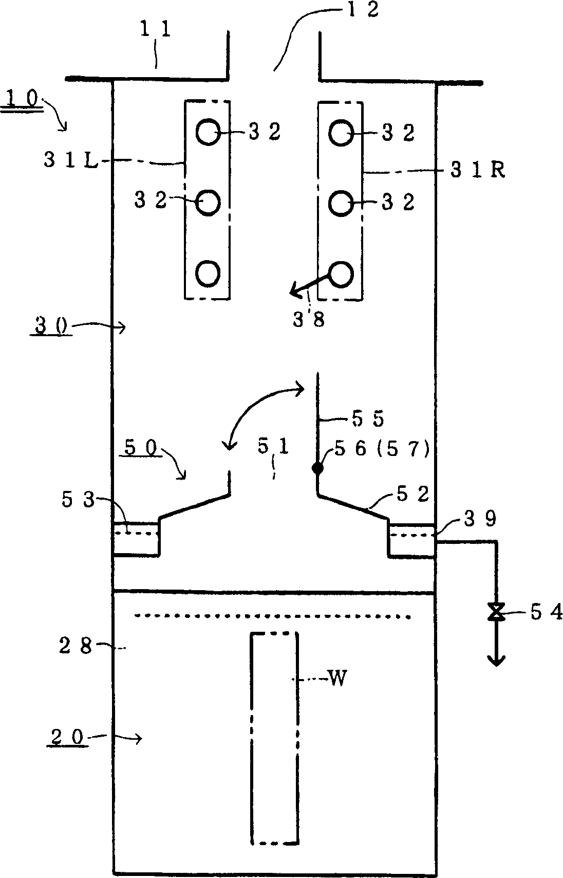
[0030] The surface treatment device such as Figure 1 to Figure 5 As shown, the basic functionality is the same as in the case of existing examples ( Image 6 ) are the same, the first surface treatment process of performing the first surface treatment on the workpiece W and the second surface treatment process of performing the second surface treatment on the workpiece W after the first surface treatment process can be performed sequentially. In addition, this surface treatment device can perform the first surface treatment while being immersed in the first treatment liquid 28 stored in the first surface treatment tank (surface treatment tank) 20, and can treat the workpiece ( The object to be treated) W is sprayed with the second treatment liquid 38 while performing the second surface treatment step. In this surface treatment device, the first surface treat...


PUM


Abstract

To shorten the exposing time from the end of a first surface treating process before the start of a second surface treating process. SOLUTION: The lower side of a booth 10 which is opened in the upper part and is intermediately partitioned by an intermediate partition 50 to form a first surface treating vessel 20 and the ascending side thereof is formed as a shower chamber 30. The intermediate partition 50 is provided with an aperture 51 which allows the passage of a work W in a vertical direction and an opening/closing cap 55 which is capable of opening and closing the aperture 51. The equipment is so formed that the first surface treating process step can be executed in the state that the work W is immersed into the first treating liquid 28 prepared in the first surface treating vessel 20 and in the state that the opening/ closing cap 55 is held closed and the second surface treating process step can be executed while the work W is showered with the second treating liquid 38 in the shower chamber 30 in the state that the opening/closing cap 55 is held closed.

Description

technical field [0001] The invention relates to a surface treatment device, which sequentially implements a first surface treatment process of using a first treatment liquid to treat the surface of a workpiece and a second surface treatment of using a second treatment liquid to perform surface treatment on the workpiece after the first surface treatment. process. Background technique [0002] like Image 6 As shown, the first surface treatment process of using the first treatment liquid 28P to carry out surface treatment on the workpiece (object to be treated) W, and the use of the second treatment liquid 38P to carry out surface treatment on the workpiece W after the first surface treatment is carried out in sequence. The surface treatment apparatus for the second surface treatment step is well known. [0003] Specifically, in Image 6 Among them, the first surface treatment tank 20P and the second surface treatment tank 30P of the whole-process immersion method device are...

Claims


Application Information

Patent Timeline
Patent Type & Authority Applications(China)
IPC IPC(8): B05D1/18B05D3/00C23F1/08C23G1/00C23G3/00
CPCC23F1/08C23G3/021C23G3/027
Inventor 渡部昌秀薄田仁志
Owner ALMEX PE INC
Why Eureka
Try Eureka