Method and device for reducing polygon effect in reversing area of pedestrain conveyor systems

A polygonal effect, the technology of the delivery system, in the direction of transport and packaging, escalators, etc.

Inactive Publication Date: 2003-04-02
KONE CORP
View PDF1 Cites 7 Cited by
  • Summary
  • Abstract
  • Description
  • Claims
  • Application Information

AI Technical Summary

Problems solved by technology

In addition to the noise generated, these periodically occurring...

Method used


Image

  • Method and device for reducing polygon effect in reversing area of pedestrain conveyor systems
  • Method and device for reducing polygon effect in reversing area of pedestrain conveyor systems

Examples


Embodiment Construction

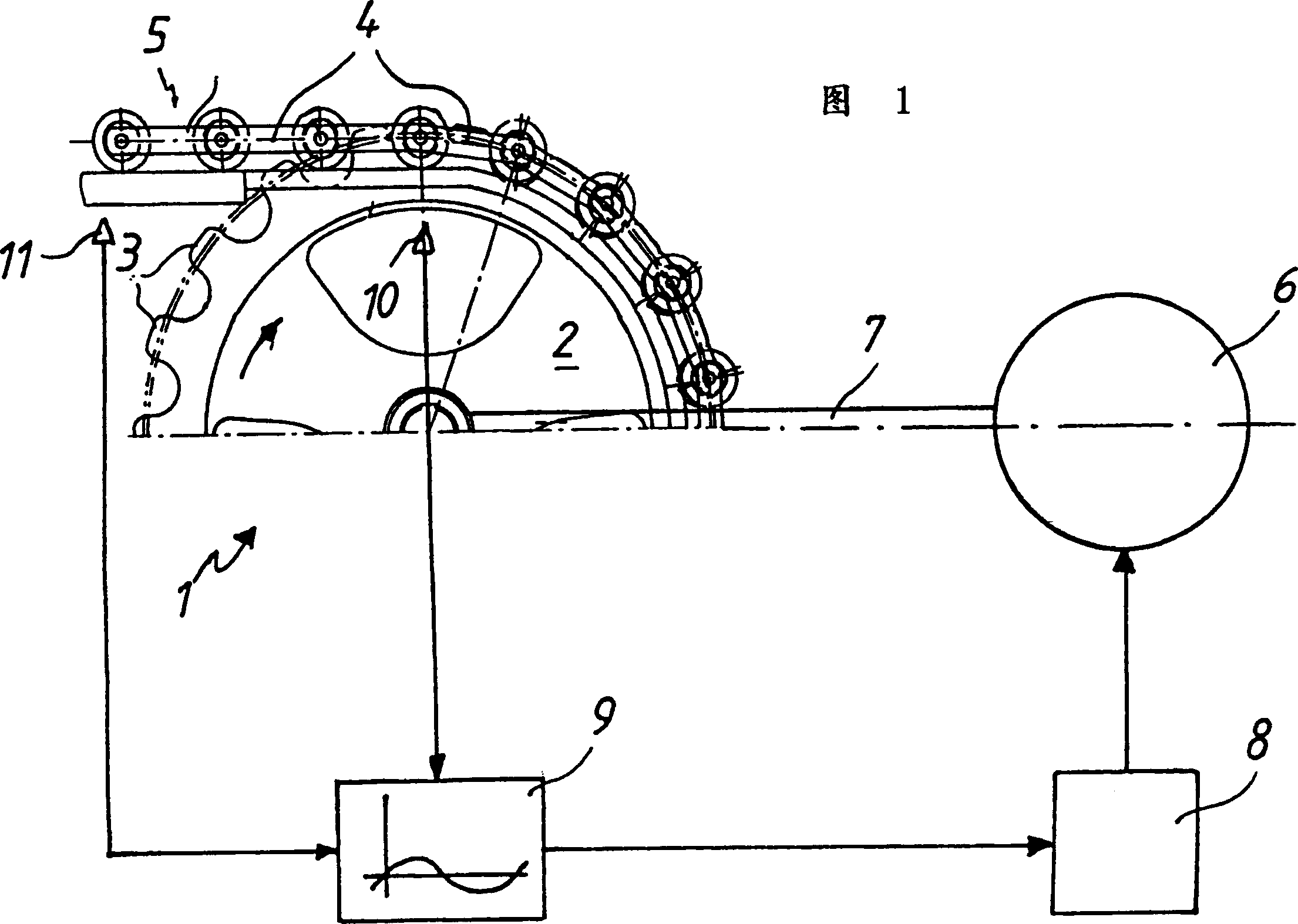
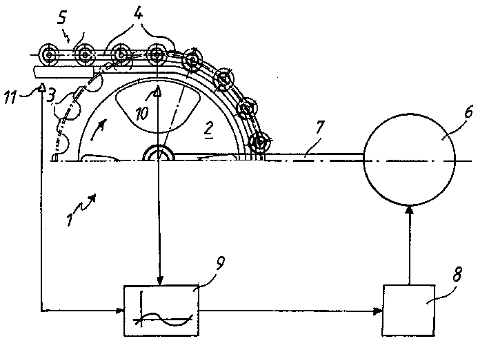
[0022] The following components can be seen: a reversing wheel 2 equipped with several gear teeth 3; a holding chain 5 composed of several chain links 4; Gears form an active relation. The connection between the drive motor 6 and the reversing wheel 2 is realized by the transmission member 7 . The walking direction of chain 5, correspondingly the reversing direction of reversing wheel 2 is indicated by each arrow. According to the invention, the polygon effect (polygon effect), which occurs during the entry of the chain 5 into the reversing wheel 2, is reduced, because a different rotational speed is superimposed on the rotational speed of the reversing wheel 2, so that the reversing wheel 2 moves at a different speed. Rotating at a constant rotational speed, which essentially corresponds to the mathematical function of the chain 5 during entry into the reversing wheel 2, so that the occurrence of shocks due to polygonal effects in the entire system is minimized.

[0023] Th...


PUM


Abstract

The invention relates to a method for reducing the polygon effect that occurs over the course of the reversing of a chain, which can be used for a pedestrian conveyor, especially an escalator or moving walkway. To this end, a different rotational speed is superimposed upon the rotational speed of the reversing wheel via the electric drive which indirectly or directly acts upon said reversing wheel.

Description

technical field [0001] The invention relates to a method for reducing the polygonal effect that occurs during a chain reversing process, which can be used in a pedestrian conveyor, in particular an escalator or a runway. Background technique [0002] With the aid of a sprocket, polygonal and rotational effects can occur in pedestrian conveyor systems, especially in the chains of escalators and walkways, which in particular have a negative effect on the smooth running of escalators or walkways. [0003] The polygon effect is caused by the square plates of the chain on the sprockets. As the angle of rotation increases, the effective radius of the sprocket changes, so that the speed of the chain oscillates between a maximum and a minimum. When the sprocket is engaged, the chain rollers and the sprocket teeth have different speeds, which creates a shock. The gyro effect is the angular momentum transferred from the sprockets to the links and thus to the decks or brackets. Afte...

Claims


Application Information

Patent Timeline
IPC IPC(8): B66B23/02
CPCB66B23/022B66B23/02
Inventor 亚历山大·皮茨
Owner KONE CORP
Why Eureka
Try Eureka