crawler walking mechanism

A traveling mechanism, tracked technology, used in tracked vehicles, motor vehicles, transportation and packaging, etc.

Active Publication Date: 2017-02-15
CATERPILLAR GLOBAL MINING HMS GMBH
View PDF11 Cites 0 Cited by
  • Summary
  • Abstract
  • Description
  • Claims
  • Application Information

AI Technical Summary

Problems solved by technology

[0010] Both variants have advantages, but similar

Method used


Image

  • crawler walking mechanism
  • crawler walking mechanism
  • crawler walking mechanism

Examples


Embodiment Construction

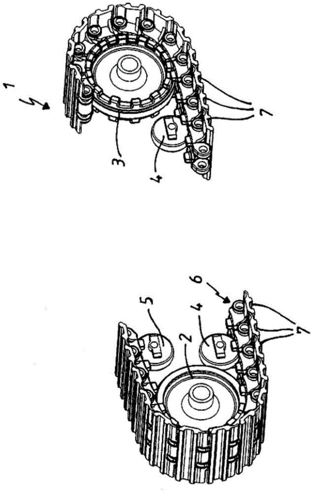
[0032] figure 1 A schematic diagram of the tracked undercarriage 1 according to the invention is shown in a perspective view. The following components can be seen: guide pulley 2 , drive pulley 3 , track pulley 4 , idler pulley 5 and endless chain 6 formed by a plurality of track shoes 7 articulated and interconnected.

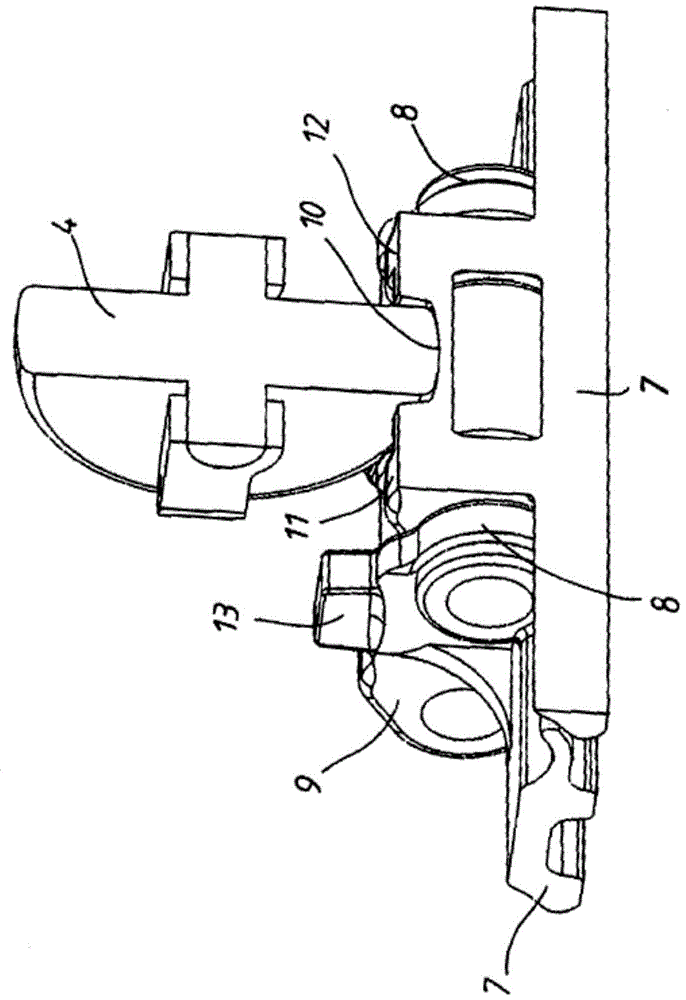
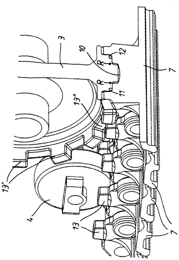
[0033] figure 2 Track shoe 7 operatively connected to track wheel 4 is shown. Connection areas 8 , 9 for receiving additional track shoes 7 can be seen. It can be seen in said figure that the track wheels 4 roll on an associated running surface 10 , which has a rectilinearly extending contour. Further running surfaces 11 , 12 are provided outside the running surface 10 for the track rollers 4 and the carrier rollers 5 , that is to say above the running surface 10 . Track shoe 7 has sprocket 13, and described sprocket is around driving wheel 3 ( figure 1 ) engages correspondingly provided tooth profile on drive wheel 3 when turning ( image 3 )middle. H...


PUM


Abstract

The invention relates to a crawler-type running gear, especially for excavators with an operating weight of more than 200 tons, the running gear has a drive wheel (3), a guide wheel (2), a plurality of crawler wheels (4), a plurality of carrier wheels ( 5) and an endless chain formed by a plurality of hingedly interconnected track shoes (7), wherein the drive wheels (3) have laterally projecting tooth profiles (13'), the track shoes (7) ) has vertically projecting teeth (13) extending parallel to each other, which engage into the tooth profile (13') when the track shoe (7) is turned around the drive wheel (3), wherein the The crawler shoes (7) form separate running surfaces (10, 10, 10, 10, 10, 10, 10, 10, 10, 10, 10, 10, 10, 10, 10, 10, 10, 10, 10, 10, 10, 10, 10, between the teeth (13) for the crawler wheel (4) and the carrier wheel (5), and for the guide wheel (2) and the driving wheel (3). 11, 12) in such a way that the running surfaces (10) for the track wheels (4) and carrier wheels (5) are substantially rectilinear and for the guide wheels (2) and drive wheels (3) The running surfaces (11, 12) are curved.

Description

technical field [0001] The invention relates to a crawler-type traveling mechanism, in particular to a crawler-type traveling mechanism for an excavator with a running weight greater than 200 tons. Background technique [0002] DE 27 20 332 A1 discloses a tracked undercarriage for vehicles, in particular hydraulic excavators equipped with special transmissions, which has a drive wheel / drive sprocket for the use of Track chain steering guide wheels, and links interconnected by pegs. An important fact in this document is the disclosure of a double web link which is manufactured from one piece and is constructed such that the link has a centrally located lug for the purpose of driving the track chain The purpose is for the tooth centrally located on the drive wheel to engage the outer flat surface of the boss. [0003] The links each have an inner lug and an outer lug in which a pin for connecting the links into a strand is received, wherein the inner lug and the outer lug fo...

Claims


Application Information

Patent Timeline
IPC IPC(8): B62D55/08B62D55/12
CPCB62D55/12B62D55/125B62D55/14B62D55/202B62D55/26B62D55/08
Inventor M·库尼克
Owner CATERPILLAR GLOBAL MINING HMS GMBH
Why Eureka
Try Eureka