

Chain conveyor with adjustable distance between axes
A conveyor and pitch technology, applied in the direction of conveyor, transportation and packaging, packaging, etc., can solve the problem that the drive is not suitable
- Summary
- Abstract
- Description
- Claims
- Application Information
AI Technical Summary
Problems solved by technology
Method used
Image

Examples
Embodiment Construction
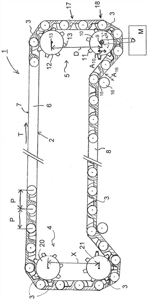
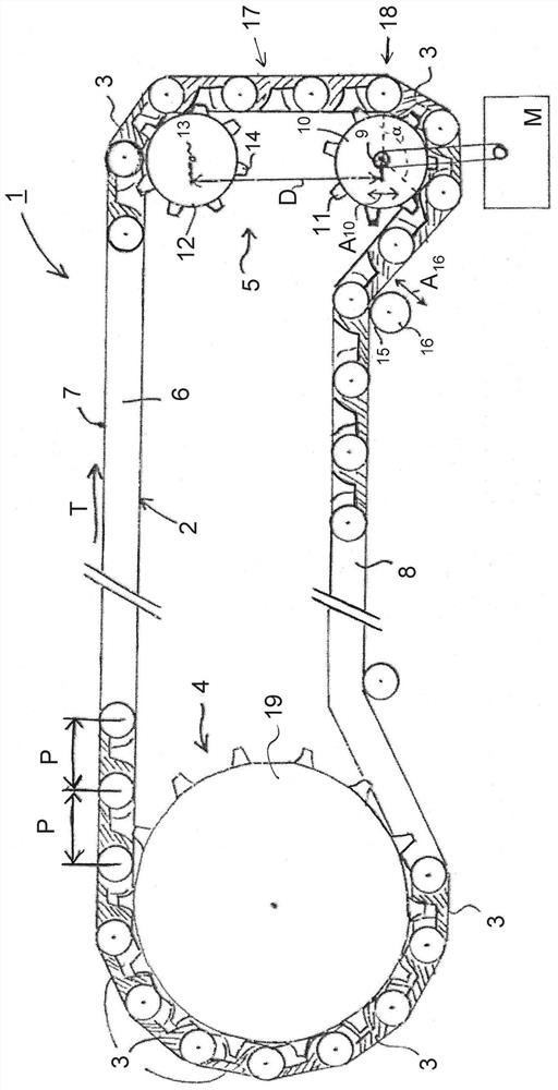
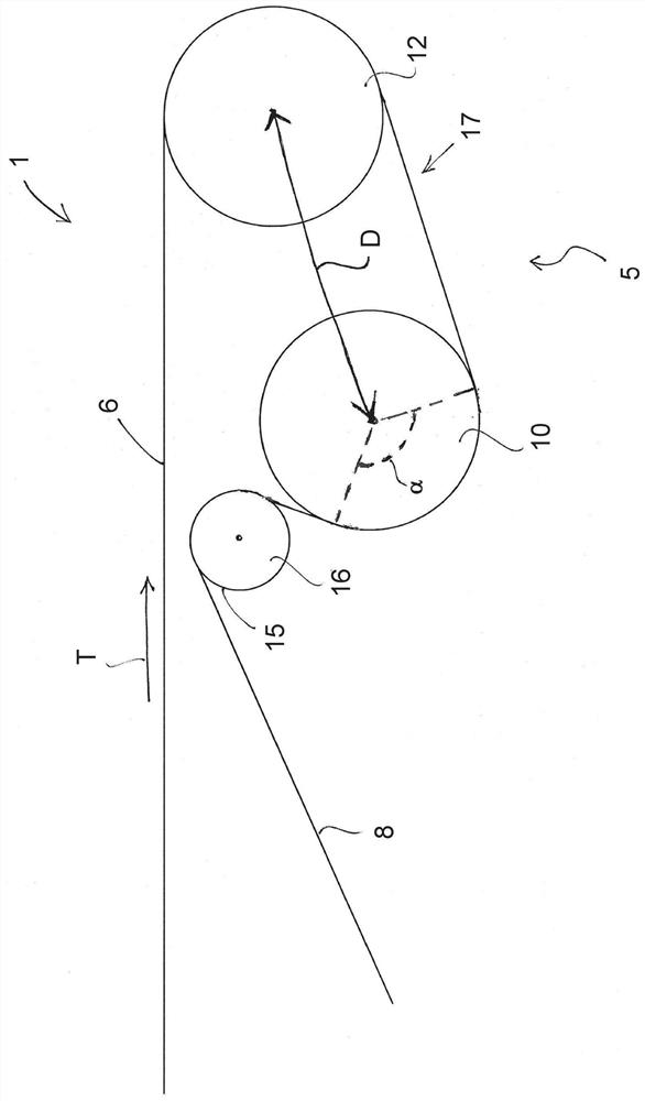
[0021]In the figures, a schematic cross-sectional view of an embodiment of a modular conveyor 1 according to the invention is shown. The modular conveyor 1 comprises a conveyor mat or conveyor chain 2 , in particular a substantially plastic conveyor mat or conveyor chain, for conveying products in the conveying direction T. The conveyor mat 2 or conveyor chain 2 comprises a succession of modules 3 or segments 3 , in particular substantially plastic modules 3 , which follow one another in the conveying direction T. Said modules 3 are hinged together forming an endless loop in a hitherto known manner. Viewed in the transport direction T, the modules 3 are each provided with hinge loops at their front and rear sides, wherein the hinge loops of successive modules 3 in the transport direction T cooperate and are connected by means of hinges extending transversely to the transport direction T. Pin connection. The hinge ring at the front side of the module is positioned at a pitch ...
PUM
 Abstract
Description
Claims
Application Information