Chain transmission and chain

A technology of chain transmission and driving device, applied in the direction of transmission device, gear transmission device, transmission chain, etc., can solve the problems of mechanical friction loss, high wear of chains and guide parts, shortening the service life of chains and guide parts, etc.

Inactive Publication Date: 2009-05-27
西奥多勒斯·亨里库斯·约翰尼斯·卡罗莱娜·科斯
View PDF6 Cites 0 Cited by
  • Summary
  • Abstract
  • Description
  • Claims
  • Application Information

AI Technical Summary

Problems solved by technology

[0008] A disadvantage of the known chain drive is that when the chain traverses a curved path, the chain link is further pivoted relative to the other link, which causes a continuous increase in the contact force between the chain and the guide
This Hertzian contact stress becomes unacceptably high if higher mechanical power is transmitted and the rotational speed is higher
At higher powers and speeds, excessive chain and guide wear can severely shorten chain and guide life
In addition, mechanical friction loss and additional noise will be generated, which are also very serious defects

Method used


Image

  • Chain transmission and chain
  • Chain transmission and chain
  • Chain transmission and chain

Examples


Embodiment Construction

[0029] It should be noted that preferred embodiments of the invention are schematically shown in the drawings, but these embodiments are only non-limiting examples. In the drawings, the same or corresponding parts are denoted by the same reference numerals.

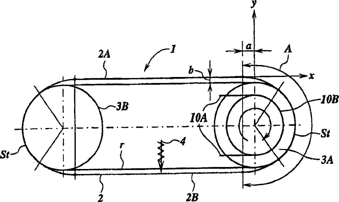
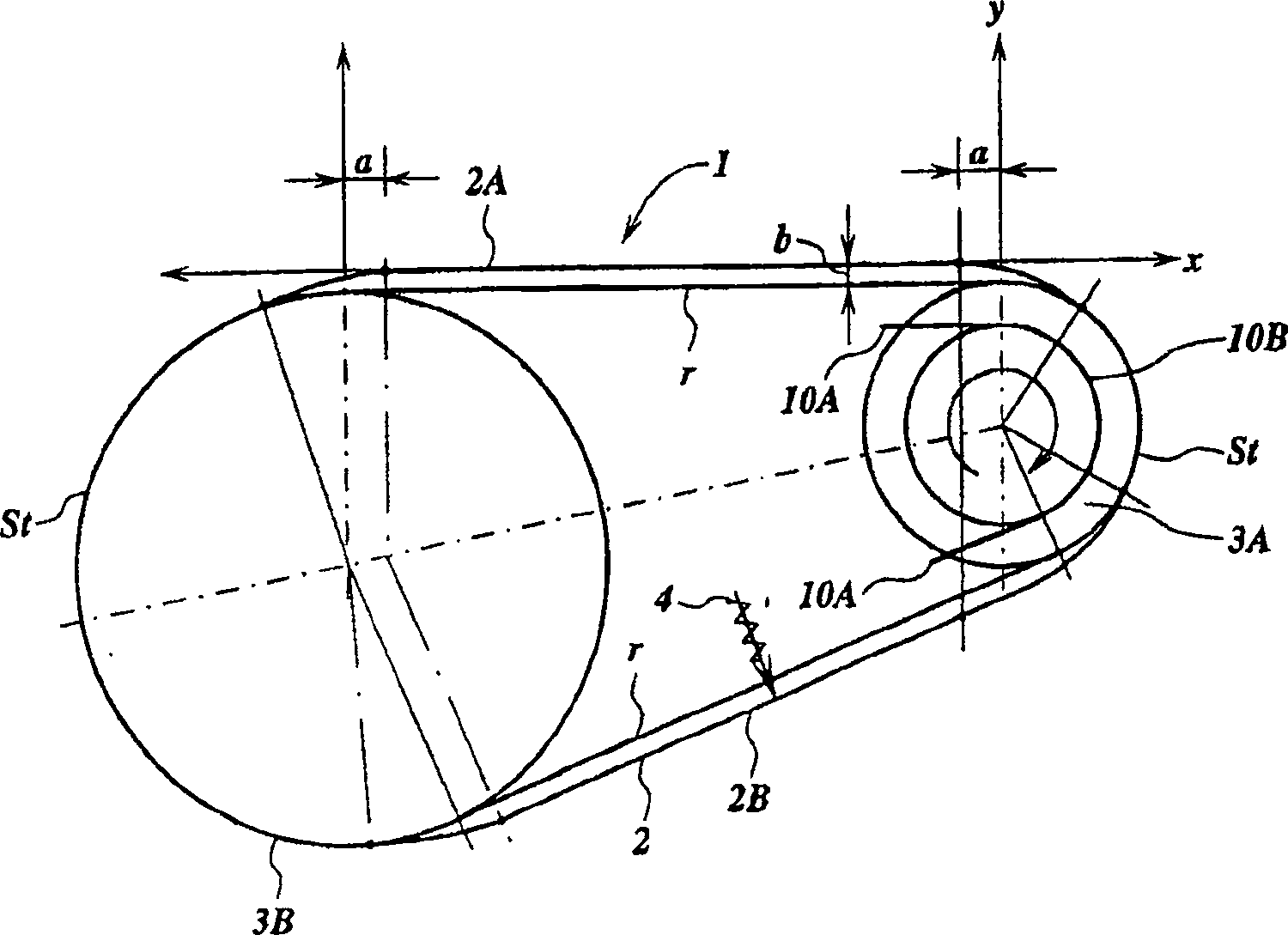
[0030] first refer to attached Figure 1A , which shows a chain drive 1 with a continuous chain 2 rotating around two sprockets 3A and 3B. The sprockets 3A and 3B are rotatably arranged and on their outer circumference are arranged teeth which, during use, interact with the continuous link 5 of the chain 2 on the engagement portion. The engagement portion around the sprocket 3A is indicated generally by the letter A in FIG. 1 . The sprocket 3A forms a driving sprocket in this embodiment, and the sprocket 3B forms a driven sprocket. The transmission ratio between the sprockets 3A and 3B is independent of the rotational position of the sprocket 3 . In this illustrative example a gear ratio equal to 1 has been chosen, how...


PUM


Abstract

The transmission has a chain (2) with successive link series (5, 5, 5) connected to one another. A wheel rotates about an axis of rotation, and a driver unit interacts with the links. A support unit with a rotation support keeps the pivot axes at a constant speed of the wheel. The support interacts with the support surfaces such that distance between axis of rotation and pivot axes (H) is variable.

Description

technical field [0001] The invention relates to a chain transmission device. A chain drive of this type is known from WO 97 / 31846. Background technique [0002] Chain drives are widely used in mechanical engineering for slip-free rotational transmission, for example when driving the camshafts of internal combustion engines. [0003] There are various designs of current chain drives. Chain drives are usually designed in the form of a continuous chain rotating around at least two sprockets, while a suitable chain tensioner may be fitted to tension the chain around said sprockets. [0004] The links of the chain can be formed in a number of ways, but generally consist of a row of connecting plates connected in sequence with the aid of pivot pins. Each link usually consists of two link plates connected in parallel and each provided with openings arranged at a distance from each other in the longitudinal direction of the chain, the link plates at the center of the pivot pin A...

Claims


Application Information

Patent Timeline
Patent Type & Authority Patents(China)
IPC IPC(8): F16H7/06F16H7/18F16G13/06F16H7/14F16G13/04F16H1/00F16H7/08
CPCF16H7/06F16H7/18F16H2007/0872F16G13/04F16G13/06F16H2007/0808F16H2007/0804F16H2007/081
Inventor 西奥多勒斯·亨里库斯·约翰尼斯·卡罗莱娜·科斯
Owner 西奥多勒斯·亨里库斯·约翰尼斯·卡罗莱娜·科斯
Why Eureka
Try Eureka