Vane blade tip structure of vane type machine

A blade type and blade technology, applied in the field of blade tip structure of blades, can solve the problems of difficult installation of rotating shrouds, reduced applicability, etc., and achieve the effect of reducing blade tip eddy current noise of blade type machinery, remarkable results, and good manufacturability.

Inactive Publication Date: 2003-04-30
王晓强
View PDF0 Cites 2 Cited by
  • Summary
  • Abstract
  • Description
  • Claims
  • Application Information

AI Technical Summary

Problems solved by technology

However, this structure forms a gap between the rotating shroud and the fixed casing. With the generation of the gap, the boundary layer noise of the ring wall is generated, forming a new noise source. At the same time, the rotating shroud is installed in many blade machines Very difficult, reducing the applicability of the method

Method used


Image

  • Vane blade tip structure of vane type machine
  • Vane blade tip structure of vane type machine
  • Vane blade tip structure of vane type machine

Examples


Embodiment Construction

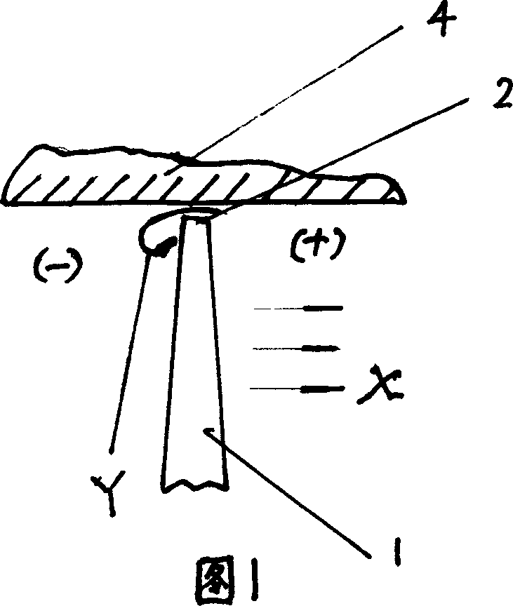
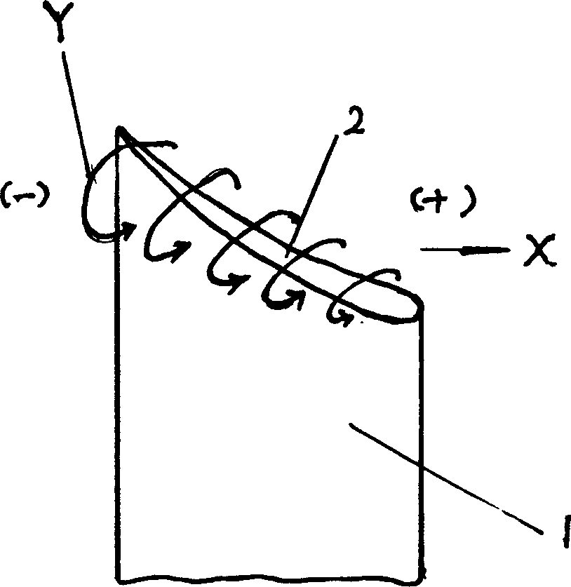
[0013] The present invention will be described in detail below in conjunction with the accompanying drawings: an axial flow fan is taken as an example to illustrate the formation reasons and control mechanism of blade tip clearance vortex noise. In the axial flow fan, with the rotation of the fan blade 1, the load on the blade increases, forming the axial movement of the airflow, that is, the mainstream X, and also forming the pressure surface and suction surface of the blade 1 increasing from the leading edge to the trailing edge of the blade. At the same time, due to the large gap between the blade tip 2 and the fan casing 4, the air flow passes through the blade tip from the pressure surface to the suction surface, forming a blade tip vortex that is constantly expanding from the leading edge to the trailing edge of the blade. Y, as shown in Figure 1 and figure 2 shown. As the blade load increases, the pressure difference between the pressure surface and the suction surface...


PUM


Abstract

The present invention relates to a blade apex structure of blade type machine, it is characterized by that a certain width is added on the circumferential direction of blade apex rotation along the blade to form blade apex secondary blade, and large quantity of concave depressions are set up on relative surface of blade apex secondary blade and blade type machine shell inner wall and further optimize the width, thickness and shape of blade apex secondary blade, thereby achieves the aim of effectively inhibit the vortex noise of blade type machine.

Description

technical field [0001] The patent of the present invention relates to the technical field of blade machinery, specifically a tip structure of a blade of blade machinery. technical background [0002] At present, in the control of blade tip clearance eddy current noise of blade machinery, the relatively successful structures mainly include: clearance reduction method and rotating shroud method. The method of reducing the gap is to reduce the gap between the tip of the blade and the casing of the blade type machine to increase the resistance to form the vortex in the tip gap, thereby reducing the formation of the vortex in the tip. In practice, this method has played a certain role in reducing the tip clearance vortex noise. However, since it is necessary to realize almost zero clearance, that is, the vortex in the blade tip clearance is not easy to form or cause little damage, it is very difficult to realize in terms of manufacturing. Using the rotating shroud method is als...

Claims


Application Information

Patent Timeline
Patent Type & Authority Applications(China)
IPC IPC(8): F04D29/24F04D29/38
Inventor 王晓强殷畅
Owner 王晓强
Why Eureka
Try Eureka