Axial flow wind wheel

An axial flow wind and wind wheel technology, which is applied to the components of the pumping device for elastic fluids, non-variable displacement pumps, machines/engines, etc., can solve the problems of low-energy fluid accumulation, high aerodynamic noise of the wind wheel, etc. To achieve the effect of reducing accumulation, reducing the weight of the wind wheel and motor load, and reducing the energy intensity

Active Publication Date: 2012-03-14
MIDEA GRP CO LTD
View PDF6 Cites 7 Cited by
  • Summary
  • Abstract
  • Description
  • Claims
  • Application Information

AI Technical Summary

Problems solved by technology

[0002] Most of the existing air-conditioning outdoor units use axial-flow wind rotors for heat dissipation. The axial-flow wind rotors include more than two blades arranged on the hub, and the blades are distributed on the hub at equal or unequal intervals around the center axis of rotation of the wind rotor. , the outer edge of the blade is a smooth spatial curve. When the axial flow rotor with this structure rotates, it is easy to cause low-energy fluid to accumulate on the ring wall of the blade, and to form a large-sized vortex on the suction surface of the blade, resulting in relatively large vortices when the rotor is running. high aerodynamic noise

Method used


Image

  • Axial flow wind wheel
  • Axial flow wind wheel
  • Axial flow wind wheel

Examples


Embodiment Construction

[0015] The present invention will be further described below in conjunction with the accompanying drawings and embodiments.

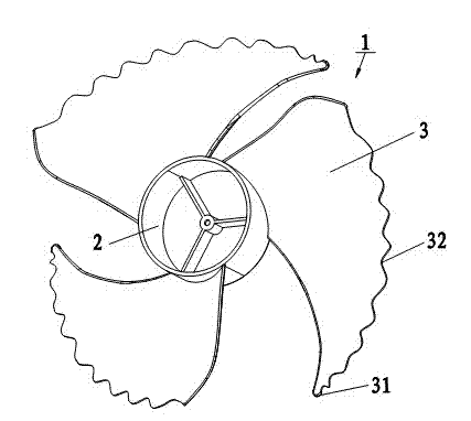
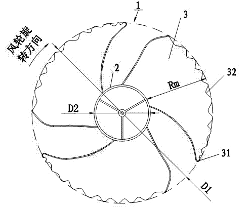
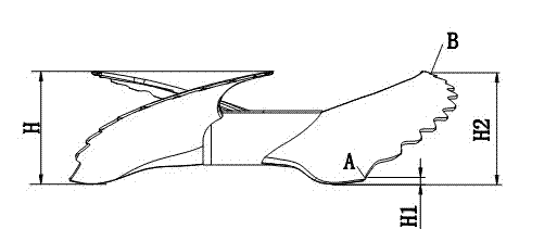
[0016] In each figure, 1 is the axial flow rotor, 2 is the hub, 3 is the blade, 31 is the outer edge of the blade, 32 is the corrugated part of the outer edge of the blade, D1 is the outer diameter of the axial flow rotor, D2 is the diameter of the hub, R m is the blade height, H is the wind rotor height, H 1 is the height of the position A where the outer edge of the blade begins to corrugate, H 2 It is the height of position B where the corrugation of the outer edge of the blade ends.

[0017] see figure 1 The axial flow wind rotor 1 includes three blades 3 arranged on the hub 2. The blades 3 have the same shape and installation angle. The blades 3 are distributed on the hub 2 at equal or unequal intervals around the center axis of rotation of the wind rotor 1. Above, the middle section of the outer edge of the blade 3 is the corrugated part 32 of...


PUM


Abstract

The invention relates to an axial flow wind wheel, which comprises more than two blades arranged on a hub, wherein the blades are distributed on the hub at equal intervals or unequal intervals by taking the rotating central axis of the wind wheel as the center. The axial flow wind wheel is characterized in that: the outer edge shape of each blade is in a wave-shaped space curve. When the axial flow wind wheel rotates, gas of the pressure surfaces of the blades flows into the suction surface in different degrees through the wave-shaped outer edges of the blades due to the wave shapes of the outer edges of the blades, so that the pressure distribution of the blades is changed, the kinetic energy of the gas on the suction surface is increased, low-energy fluid can be prevented from accumulating at the annular walls of the blades, large eddy turbulence is destructed, blade tip vortex and trailing edge falloff are effectively refined, the energy strength of the vortex is reduced, and the vortex noise of the wind wheel is restricted, therefore the noise of the wind wheel is effectively reduced, the acoustic quality is softer and more comfortable, meanwhile, the wind wheel weight and the motor load are lightened by wave shapes of the outer edges of the blades, and the wind wheel cost and the motor power are reduced. The invention is especially suitable for an outdoor unit of an air-conditioner.

Description

technical field [0001] The invention relates to an axial flow wind wheel, in particular to an axial flow wind wheel suitable for an air conditioner outdoor unit. Background technique [0002] Most of the existing air-conditioning outdoor units use axial-flow wind rotors for heat dissipation. The axial-flow wind rotors include more than two blades arranged on the hub, and the blades are distributed on the hub at equal or unequal intervals around the center axis of rotation of the wind rotor. , the outer edge of the blade presents a smooth spatial curve. When the axial-flow rotor with this structure rotates, it is easy to cause low-energy fluid to accumulate on the ring wall of the blade, and to form a large-sized vortex on the suction surface of the blade, resulting in relatively large vortices during the operation of the rotor. High aerodynamic noise. According to the experimental analysis, 50%-70% of the noise of the outdoor unit is caused by the aerodynamic noise of the a...

Claims


Application Information

Patent Timeline
Patent Type & Authority Applications(China)
IPC IPC(8): F04D29/32F04D29/38
Inventor 马丽华游斌易正清李跃飞韦福权
Owner MIDEA GRP CO LTD
Why Eureka
Try Eureka