Centrifugal wind wheel with flow guide device

A technology of flow guiding device and centrifugal wind wheel, which is applied to components of pumping devices for elastic fluids, non-variable pumps, machines/engines, etc., and can solve problems such as unresolved airflow and increasing the working area of ​​blades , to achieve the effect of smooth airflow, reducing eddy current and reducing eddy current separation

Active Publication Date: 2018-12-28
FANS TECH ELECTRIC CO LTD
View PDF9 Cites 3 Cited by
  • Summary
  • Abstract
  • Description
  • Claims
  • Application Information

AI Technical Summary

Problems solved by technology

In this application, the guide ring is used to increase the height of the air outlet of the centrifugal fan, which increases the height of the blade and its actual working area, thereby effectively increasing the contact area between the heat exchanger of the ceiling machine and the airflow. Large heat exchange efficiency can be effectively improved, but the guide ring does not solve the problem that the airflow is easy to form a vortex when it is discharged from the flow channel between the blades

Method used


Image

  • Centrifugal wind wheel with flow guide device
  • Centrifugal wind wheel with flow guide device
  • Centrifugal wind wheel with flow guide device

Examples


Embodiment 1

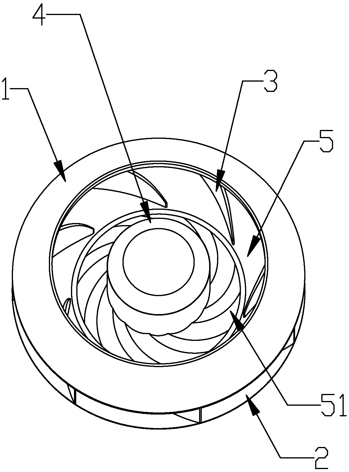
[0036] like figure 1 As shown, a centrifugal wind rotor with deflector 5 includes a front disc 1 of the rotor, a rear disc 2 of the rotor, a motor mounting part 4, and rotor blades 3, and the rotor blades 3 are arranged obliquely or vertically on the Between the front disk 1 of the wind rotor and the rear disk 2 of the wind rotor, and the upper and lower ends of the blades 3 of the wind rotor are respectively connected with the front disk 1 of the wind rotor and the rear disk 2 of the wind rotor. The motor installation part 4 is arranged at the center of the wind rotor rear panel 2, and the motor installation part 4 is used for connecting with the bottom of the motor. The centrifugal wind rotor also includes a deflector 5, which is arranged on the rear plate 2 of the wind rotor and placed between the motor mounting part 4 and the blades 3 of the wind rotor. The deflector 5 It can be integrally formed with the rear disk 2 of the wind rotor or installed on the rear disk 2 of th...

Embodiment 2

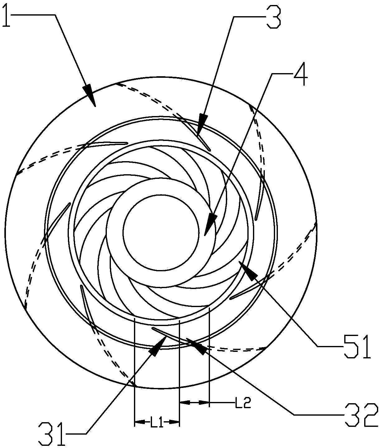
[0044] like Figure 5 As shown, this embodiment only describes the difference from the above embodiment, and the rest of the technical features are the same as the above embodiment. In this embodiment, the number of the guide channels 51 is consistent with the number of the wind rotor blades 3 , that is, each blade channel of the rotor blade 3 corresponds to one guide channel 51 . It is ensured that when the wind rotor rotates, the airflow of the wind rotor rear disk 2 will flow into the blade flow channels of the wind rotor blades 3 along the flow guide flow channel 51 of the flow guide device 5 .

Embodiment 3

[0046] like Image 6 As shown, this embodiment only describes the difference from the above embodiment, and the rest of the technical features are the same as the above embodiment. The end of each diversion flow channel 51 adjacent to the motor mounting part 4 is the initial end 511 of the flow channel, and the circumferential profile of the initial end 511 of the flow channel is a single arc or multiple arcs, so The multiple arcs include at least two arcs with different arc lengths.

[0047] In this embodiment, preferably, the profile line of the initial end 511 of each flow guide channel 51 along the circumferential direction is a double arc, and the double arc is connected with the suction surface 31 of the wind rotor blade. The radius of the arc in the similar direction is R1, and the width of the arc is A1; the radius of the arc in the direction close to the pressure surface 32 of the wind rotor blade in the double arc is R2, and the width of the arc is A2, and the doubl...


PUM


Abstract

The invention discloses a centrifugal wind wheel with a flow guide device. The centrifugal wind wheel comprises a motor, a front wind wheel plate, a rear wind wheel plate, the flow guide device and aplurality of blades. The flow guide device is disposed between the motor and the blades and provided with a plurality of flow guide passages, a blade flow passage of one blade corresponds to one or more flow guide passages, and the flow guide device can be integrally formed with the rear wind wheel plate or separately mounted on the same. With the aid of the flow guide device, airflow of the rearwind wheel plate can flow into the blades along the blade flow passages when the wind wheel rotates. The centrifugal wind wheel with the flow guide device has the advantages that eddy at the joint ofthe motor and the rear wind wheel plate can be reduced, airflow at the inlets of blades can be smoother, and eddy separation on the blade suction surfaces can be reduced, so that the working efficiency of the wind wheel is effectively improved and wind wheel eddy noise is lowered.

Description

technical field [0001] The invention relates to the field of fans, in particular to a centrifugal wind wheel with a guide device. Background technique [0002] The centrifugal wind wheel refers to the wind wheel that enters the wind in the axial direction and outputs the wind in the radial direction, and uses the centrifugal force to do work to increase the pressure of the air. The center of the wind wheel in the centrifugal wind wheel is the air inlet. The air intake is inhaled, and at the same time, the rotation of the wind wheel exerts a dynamic effect on the airflow, increasing the pressure and speed of the gas. Under the action of centrifugal force, the airflow is discharged along the outlet of the blade flow path between the blades in the impeller. The blades of the existing centrifugal wind rotor are all arc-shaped blades, and when the air flow is discharged from the flow passage between the blades, vortices are easily formed, which reduces the working efficiency of t...

Claims


Application Information

Patent Timeline
Patent Type & Authority Applications(China)
IPC IPC(8): F04D29/28F04D29/66
CPCF04D29/281F04D29/666F04D29/667
Inventor 莫远忠
Owner FANS TECH ELECTRIC CO LTD
Why Eureka
Try Eureka