Axial flow blower

A technology of axial flow fan and shaft sleeve, which is applied in the direction of mechanical equipment, machine/engine, liquid fuel engine, etc., and can solve problems such as exhaust noise

Pending Publication Date: 2017-08-18
ZHEJIANG SCI-TECH UNIV
View PDF8 Cites 9 Cited by
  • Summary
  • Abstract
  • Description
  • Claims
  • Application Information

AI Technical Summary

Problems solved by technology

If the fan outlet is directly discharged int

Method used


Image

  • Axial flow blower
  • Axial flow blower
  • Axial flow blower

Examples


Embodiment Construction

[0028] The present invention will be further described below in conjunction with the accompanying drawings and embodiments.

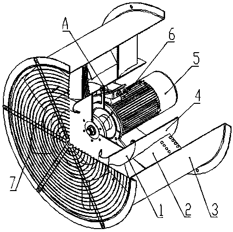
[0029] like figure 1 As shown, the axial flow fan consists of 7 parts, including 1, impeller 2, guide vane 3, outer cylinder 4, inner cylinder 5, motor 6, bushing 7, net cover; outer cylinder 3, guide vane 2 and inner cylinder 4 are fixed together by welding, the motor 5 is fixed on the web of the inner cylinder 4, the working parameters of the motor 5 are 720r / min, and the power is 4KW; the impeller 1 is fixed on the shaft of the motor 5 through the bushing 6, and the impeller 1 The gap between the wheel hub and the inner cylinder 4 is 10mm; the net cover 7 is installed on the outer cylinder 3, and has the functions of rectifying and preventing foreign matter from entering.

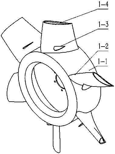
[0030] like figure 1 , 3 As shown, the impeller 1 is driven by the motor 5 to do work for the gas to increase the dynamic pressure and static pressure of the gas. The blades 1-...


PUM

PropertyMeasurementUnit
Depthaaaaaaaaaa
Thicknessaaaaaaaaaa

Abstract

The invention discloses an axial flow blower, which comprises a net cover, an impeller, a guide vane, an inner cylinder, an outer cylinder, a motor and a shaft sleeve. The net cover is fixed on the outer cylinder, is of a concentric structure and is formed by weaving iron wires; the impeller comprises a wheel hub and vanes, and the vanes are airfoil vanes which are designed through a constant circulation isolated airfoil method; a fin-shaped vortex breaking structure is arranged on a part, close to the root, of the suction surface of each vane; the top parts of the vanes are machined into an airfoil groove structure; and a labyrinth seal structure is formed in a gap between the wheel hub of the impeller and the inner cylinder. The shark fin-like vortex breaking plate is additionally arranged on the part, close to the root, of the suction surface of each vane of the impeller of the axial flow blower, the airfoil groove is formed in the top of each vane of the axial flow blower, and the labyrinth seal structure is formed in the gap between the wheel hub of the impeller and the inner cylinder, and different positions of the axial flower blower are improved, so that the efficiency of the axial flow blower is relatively high, the noise is relatively low, and the energy conservation and environment protection are achieved preferably.

Description

technical field [0001] The invention belongs to the field of fans, and in particular relates to an axial flow fan with a shark-fin-like vortex-breaking structure on the blade suction surface and double-row circular hole grooves on the guide vanes. Background technique [0002] The axial flow fan is a machine that relies on the input mechanical energy to increase the gas pressure and discharge the gas. It is widely used in ventilation, dust extraction and cooling of factories, mines, tunnels, cooling towers, vehicles, ships and buildings; ventilation and induction of boilers and industrial furnaces; cooling and ventilation in air conditioning equipment and household appliances ; Grain drying and selection; wind tunnel wind source and hovercraft inflation propulsion, etc., have very important applications in various industries of the national economy. According to statistics, the power consumption of fans accounts for about 10% of the country's power generation, and the avera...

Claims


Application Information

Patent Timeline
IPC IPC(8): F04D25/08F04D29/32F04D29/38F04D29/70
CPCF04D25/08F04D29/325F04D29/384F04D29/703
Inventor 窦华书毛涵韬徐金秋魏义坤陈小平姜陈锋陈兴贺磊盈董若凌赵新龙
Owner ZHEJIANG SCI-TECH UNIV
Why Eureka
Try Eureka