Road traffic status detecting method

A detection method and road traffic technology, applied in the field of traffic management, can solve problems such as unreasonable economic angle, inability to monitor traffic conditions, and large investment

Inactive Publication Date: 2003-05-14
陈少元
View PDF0 Cites 13 Cited by
  • Summary
  • Abstract
  • Description
  • Claims
  • Application Information

AI Technical Summary

Problems solved by technology

However, these technologies are only applied to some important traffic sections, and cannot monitor the traffic conditions in any place on each road. Even if the

Method used


Image

  • Road traffic status detecting method
  • Road traffic status detecting method
  • Road traffic status detecting method

Examples


Embodiment Construction

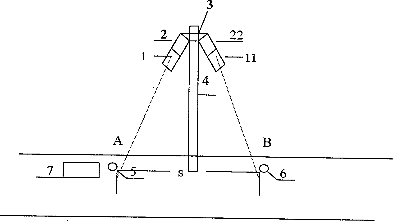
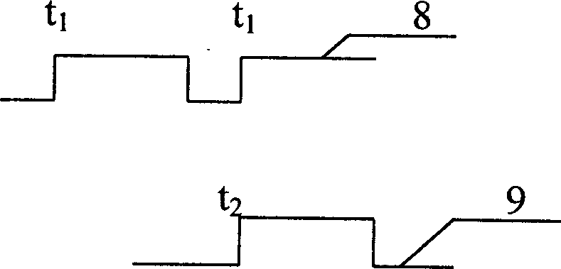
[0014] The method of the present invention can be realized in the following manner, as figure 1 Two infrared pyroelectric detection sensors are installed on the upper ends of the existing street light poles or utility poles and other supports 4 on both sides of the road, respectively denoted as detection sensor 1 and detection sensor 11, and the monitoring point A of detection sensor 1 on the road is defined As monitoring point 5 , monitoring point B on the road where the detection sensor 11 is detected is defined as monitoring point 6 . Adjust the depression angle of the detection sensor 1 and the detection sensor 11 so that the distance between the monitoring point 5 and the monitoring point 6 is 4 meters. When the front of the vehicle 7 arrives at the monitoring point 5, as figure 2 The detection sensor 1 starts to trigger high level and record the time t at this time 1 , before the trigger moment when the detection sensor 1 is ready to test the head of the next vehicle, ...


PUM


Abstract

In the present invention, a set of sensors is regulated to proper length between detection points, two detecting sensors are used to detect the times for some automobile head to the detecting points separately, and thus the time difference for the automobile to pass through the distance between the detecting points and the automobile speed are calculated by the comparison and processing system while corresponding code number is given. Then, the code number is transmitted to the traffic detection center via available mobile communication network. The present invention makes it possible for thedrivers to understand the specific traffic state in every road.

Description

technical field [0001] The invention relates to the field of traffic management, in particular to a method for detecting traffic conditions. Background technique [0002] Among the existing traffic management methods, there are many solutions for applying electronic technology, such as setting up monitors in some important traffic areas to monitor the state of vehicle flow in this area, and transmitting traffic conditions at any time to traffic control through various wired or wireless methods In the center, the traffic control center will provide timely relief for each important road section and feed back the vehicle operation conditions of these important traffic sections to the driving driver, so that the driver can grasp the traffic status of other road sections at any time. However, these technologies are only applied to some important traffic sections, and cannot monitor the traffic conditions in any place on each road. Even if the above-mentioned methods are used in e...

Claims


Application Information

Patent Timeline
IPC IPC(8): G08G1/00G08G1/01
Inventor 陈少元
Owner 陈少元
Why Eureka
Try Eureka