Pick-up feeder, information regenerator and information recorder

A feeding device and information recording technology, which is applied in data recording, information storage, recording information storage, etc., can solve the problems of difficulty in miniaturization of the device, large size of resin spring, and large friction load, etc., to prevent recording/reproduction quality The effect of lowering, reducing the load, and reducing the imparting force

Inactive Publication Date: 2003-05-14
RICOH KK
View PDF2 Cites 5 Cited by
  • Summary
  • Abstract
  • Description
  • Claims
  • Application Information

AI Technical Summary

Problems solved by technology

[0013] However, in Japanese Patent Application Laid-Open No. 11-185407, even if the arm is deflected, the distance between the tooth top and the screw does not change. Therefore, if there is an error in the relative distance between the guide member of the pickup and the screw or the size of the arm, the The top of the tooth cannot push the lead screw with a proper force, and it may not fit well in the contact part, or the friction load will become larger
[0014] In the technology described in JP-A-2000-67534, since the size of the resin spring in the longitudinal direction and the thickness direction is large, it is difficult to miniaturize the device.
In particular, in a thin optical disc device built into a notebook computer, miniaturization is required not only in the height direction but also in the axial direction of the screw, and the resin spring part interferes with the motor that drives the screw to rotate, making miniaturization impossible

Method used


Image

  • Pick-up feeder, information regenerator and information recorder
  • Pick-up feeder, information regenerator and information recorder
  • Pick-up feeder, information regenerator and information recorder

Examples


Embodiment Construction

[0067] Hereinafter, embodiments of the present invention will be described in detail with reference to the drawings.

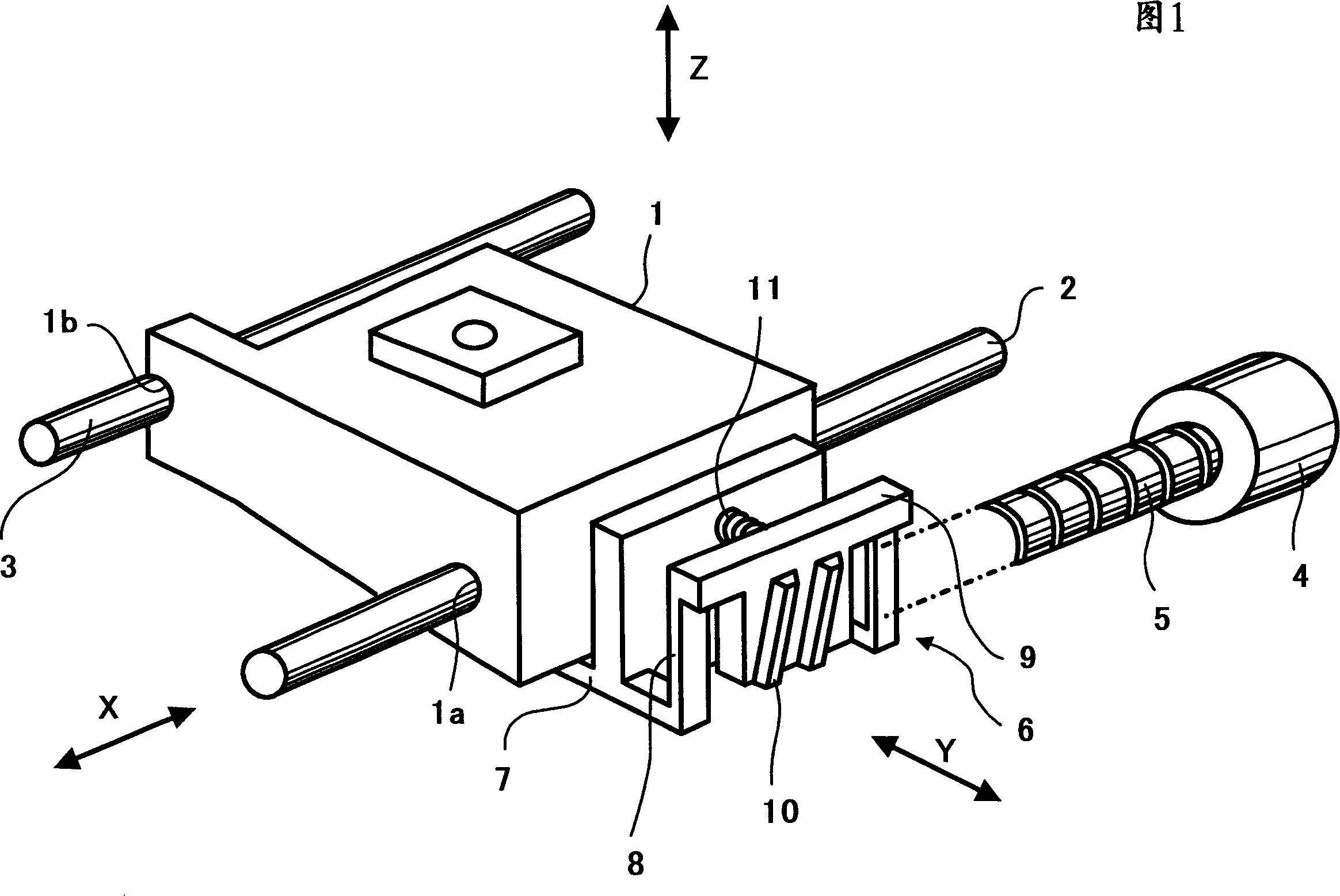
[0068] Fig. 1 is the perspective view of the device structure of the first embodiment of the present invention, among the figure, symbol 1 represents the pick-up that carries various optical parts for making the light irradiate the optical disc, and 2 represents that pick-up 1 is carried out along the radial direction of the optical disc. The first guide shaft for guidance, 3 represents the second guide shaft arranged in parallel with the above-mentioned first guide shaft 2, and guides the pickup 1 along the radial direction of the disc, 4 represents the motor, and 5 represents the lead screw composed of a cylindrical shaft , A helical groove is provided on the cylindrical shaft. The above-mentioned lead screw 5 is connected with the motor 4 and is driven to rotate. At this time, the central axis of the above-mentioned lead screw 5 coincides with the rotation...


PUM


Abstract

The present invention ralates to a pick-up feeder to move the optic pick-up feeder, information regenerator and information recorder. A rack portion 9 is provided thereon with gear teeth 10 to be engaged with grooves 1b of a lead screw 5; a connecting portion 8 with a plate spring property for connecting the rack portion 9 to a fixing portion is tightened to a pickup 1 and for supporting the rack portion 9 in a cantilever fashion to be deformable in a direction of either bringing close to, or removing from, the lead screw 5; and a compressed coil spring 11 is placed between the pickup 1 and the rack portion 9; in which the distance in the extension direction of the connecting portion 8 when viewing the axial direction of the lead screw 5 from an end on the side of the fixing portion 7 to a contact portion between the gear teeth 10 and the lead screw 5 is made smaller than the distance from an end on the side of the fixing portion 7 to another end on the side of the rack portion 9. In addition, the reduction of frictional loads, the increase in record / playback signal qualities, high speed access, and miniaturization can be achieved for the pickup drive unit.

Description

technical field [0001] The present invention relates to a pickup feeding device for moving an optical pick-up, an information reproducing (reproducing) device, and an information recording device. The optical pickup irradiates light to an optical information recording medium. Background technique [0002] Figure 11 It is a perspective view showing the structure of a conventional pickup feeding device, and symbol 61 denotes a pickup mounted with various optical components for making light irradiate an optical disc, and 62 denotes a pick-up operation when the pickup 61 is searched and moved along the radial direction of the optical disc. 61 guides the guide shaft, 63 denotes a screw consisting of a cylindrical shaft on which a helical groove is provided, and 64 denotes a motor. The screw 63 is connected to a motor 64 and is driven to rotate. At this time, the central axis of the screw 63 is aligned with the rotation axis of the motor 64 and connected. ...

Claims


Application Information

Patent Timeline
Patent Type & Authority Applications(China)
IPC IPC(8): G11B21/02G11B7/085
CPCG11B7/08582
Inventor 大野武英
Owner RICOH KK
Why Eureka
Try Eureka