Controller of three-level output single-phase step-up power factor correcting circuit

A power factor correction and control device technology, applied in battery circuit devices, circuit devices, transportation and packaging, etc., can solve the problem of slow control loop response, difficult design of RMS filter circuit, and difficulty in taking into account the mains input PFC and battery upgrades. Pressure working status, etc.

Inactive Publication Date: 2003-06-04
ZTE CORP
View PDF0 Cites 10 Cited by
  • Summary
  • Abstract
  • Description
  • Claims
  • Application Information

AI Technical Summary

Problems solved by technology

[0009] In the control circuit of the existing three-level output single-phase Boost PFC circuit, since the mains input and the battery input voltage signal sampling circuit share a set of circuits, it is difficult to design the effective value filter circuit, and the failure caused by the use of large capacitors cannot be avoided. The response of the control loop is slow. In the application of UPS, it is difficult for the input voltage signal sampling circuit 101 to take into account the two working states of mains input PFC and battery boost.

Method used


Image

  • Controller of three-level output single-phase step-up power factor correcting circuit
  • Controller of three-level output single-phase step-up power factor correcting circuit
  • Controller of three-level output single-phase step-up power factor correcting circuit

Examples


Embodiment Construction

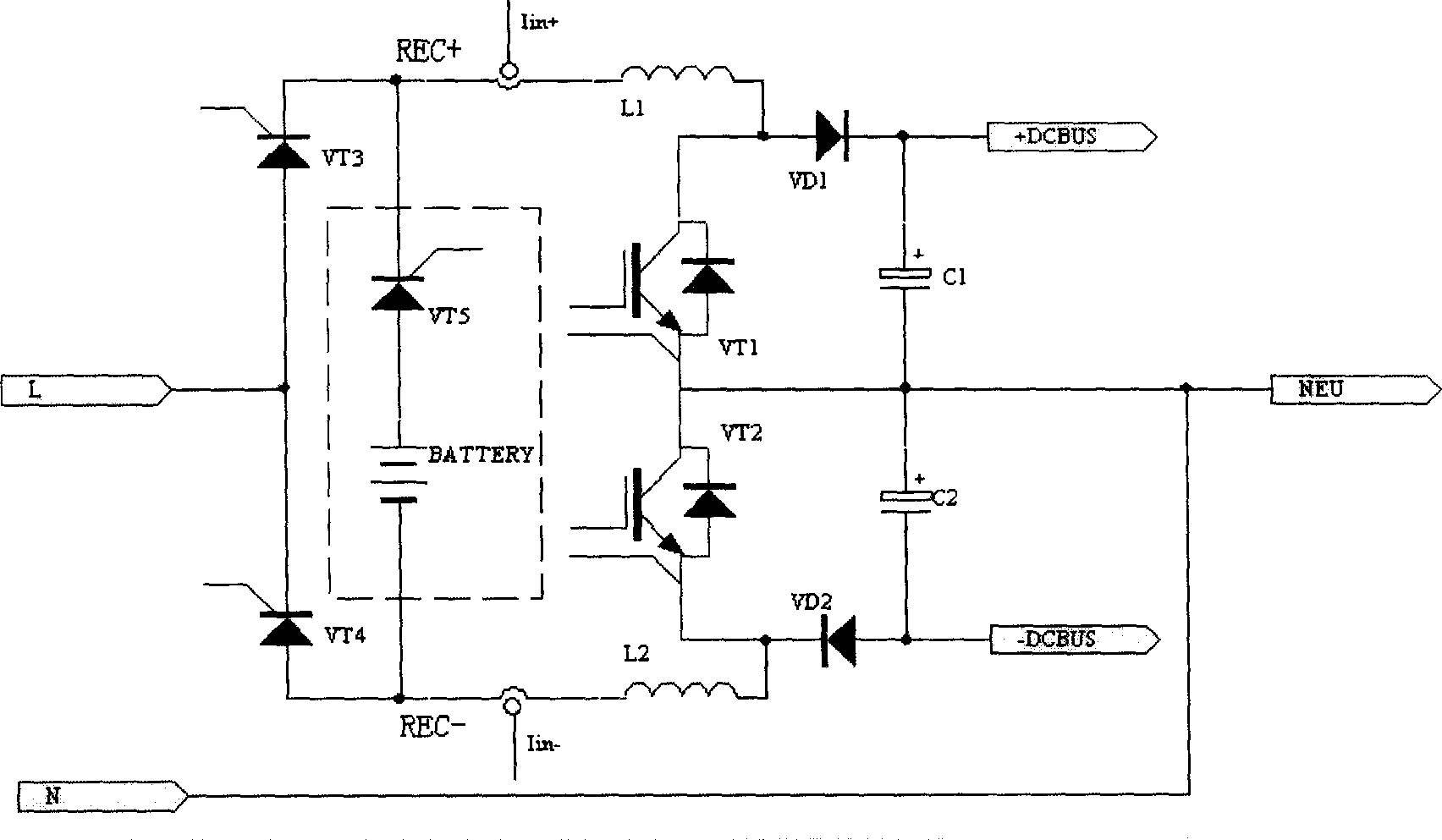
[0021] figure 1 , figure 2 , image 3 It has been described in detail in the background art section.

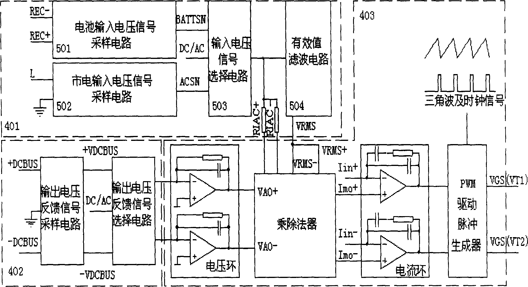
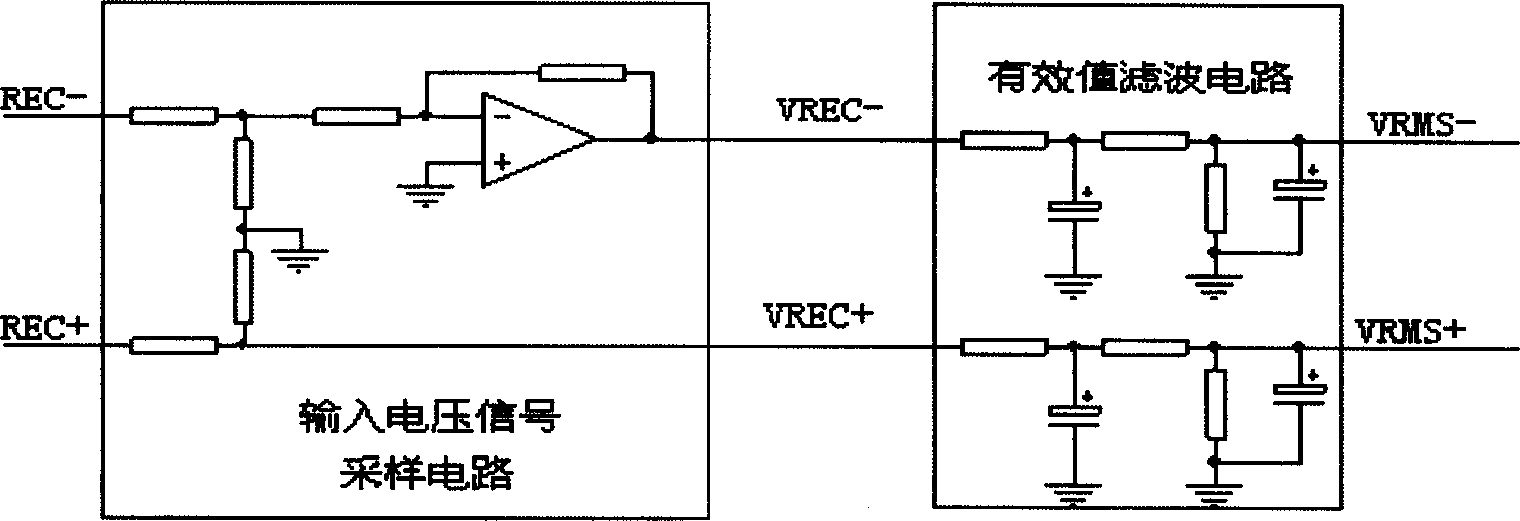
[0022] Figure 4 It is a functional block diagram of the present invention. This description proposes a control device for a three-level output single-phase boost power factor correction circuit, including an input voltage sampling part 401, an output voltage sampling part 402, and a control loop part 403, which is characterized in that the input voltage sampling part 401 includes a battery input voltage signal sampling circuit 501, a mains input voltage signal sampling circuit 502, a selection circuit 503 for two signals, and a shared effective value filter circuit 504; the battery input voltage signal sampling circuit 501 converts the battery voltage ( When the battery is working, that is, the voltage between REC+ and REC-) is converted into a battery voltage signal BATTSN; the mains input voltage signal sampling circuit 502 converts the mains input (L, N) voltage into a...


PUM


Abstract

The control circuit of three-level output single-phase Boost PFC circuit with both commercial power input PFC function and battery step-up function includes input voltage sampling part, output voltage sampling part and control loop part. The input voltage sampling part includes battery input voltage signal sample circuit to convert battery voltage into signal BATTSN, commercial power input voltage signal sample circuit to convert the commercial power input voltage into signal ACSN, selecting circuit to feed the signal BATTSN to ACSN to subsequent effective value filter circuit with the gated signal being also used as the current following signal as control loop input, and effective value filter circuit to filter the signal BATTSN or ACSN or obtain the effective value signal for the control of the loop. The present invention is easy to design and debug.

Description

technical field [0001] The invention relates to a control circuit of a three-level output single-phase step-up power factor correction (Boost PFC) circuit which has the functions of mains input power factor correction (PFC) and battery voltage boosting. Background technique [0002] figure 1 Shown is a commonly used single-phase Boost PFC circuit with three-level output. Its outstanding feature is that the ground wire N of the mains input runs through from the input to the output, and serves as the zero-level NEU of the output, and the other two output voltages Ping is positive DC level +DCBUS and negative DC level -DCBUS, so it is called a single-phase Boost PFC circuit with three-level output. This circuit is equivalent to two common single-phase Boost PFC circuits connected in parallel through NEU, which are respectively called positive Boost PFC circuit and negative Boost PFC circuit. The connection relationship of the positive Boost PFC circuit is: the mains input liv...

Claims


Application Information

Patent Timeline
Patent Type & Authority Applications(China)
IPC IPC(8): H02J7/00
CPCY02P80/10
Inventor 罗勇李艳玲徐波
Owner ZTE CORP
Why Eureka
Try Eureka