Video coder

A video coding and coding technology, applied in the direction of digital video signal modification, code conversion, pulse modulation TV signal transmission, etc. The effect of preventing extreme deterioration of smoothness and preventing extreme deterioration of picture quality

Inactive Publication Date: 2003-07-09
PANASONIC CORP
View PDF1 Cites 7 Cited by
  • Summary
  • Abstract
  • Description
  • Claims
  • Application Information

AI Technical Summary

Problems solved by technology

[0017] Conversely, with a large threshold, constant picture quality enhancement is only performed on images that fully match the pattern, resulting in a lower probability that the picture quality of important regions will be boosted
On the other hand, picture quality degradation in important regions with high probability of important regions does not satisfy the threshold
[0018] If the constant improvement of picture quality is performed only for the region having the degree of conformity with the important region equal to or greater than the threshold value regardless of the degree of conformity, the enhancement of picture quality cannot be performed by the degree of conformity, and in some cases the degree of conformity of the important region sharpness deterioration

Method used


Image

  • Video coder
  • Video coder
  • Video coder

Examples


no. 1 example

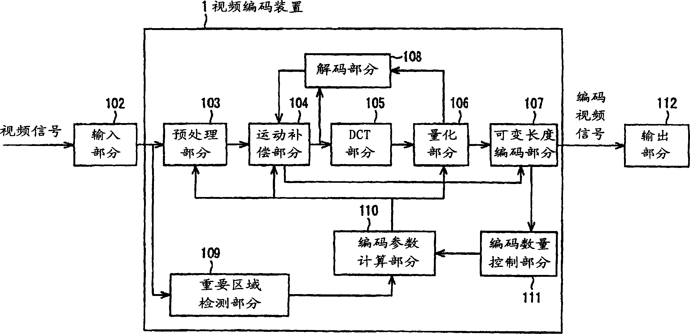
[0056] figure 1is a block diagram showing the structure of the first embodiment of the video coding apparatus according to the present invention. The video encoding device 1 according to the embodiment is composed of: a preprocessing section 103 for performing prefiltering and preprocessing of an input video so as to cut out the video in units of small blocks; a motion compensation section 104 having three operation modes, For predicting and compensating the motion of the video input from preprocessing section 103; DCT section 105 is used for orthogonal transform (discrete cosine transform) difference value or video signal itself output from motion compensation section 104; Quantization section 106 is used for The processing of quantized data is performed in the frequency region orthogonally transformed by the DCT section 105; the variable-length encoding section 107 is configured to perform variable-length encoding so that the data quantized by the quantization section 106 i...

no. 2 example

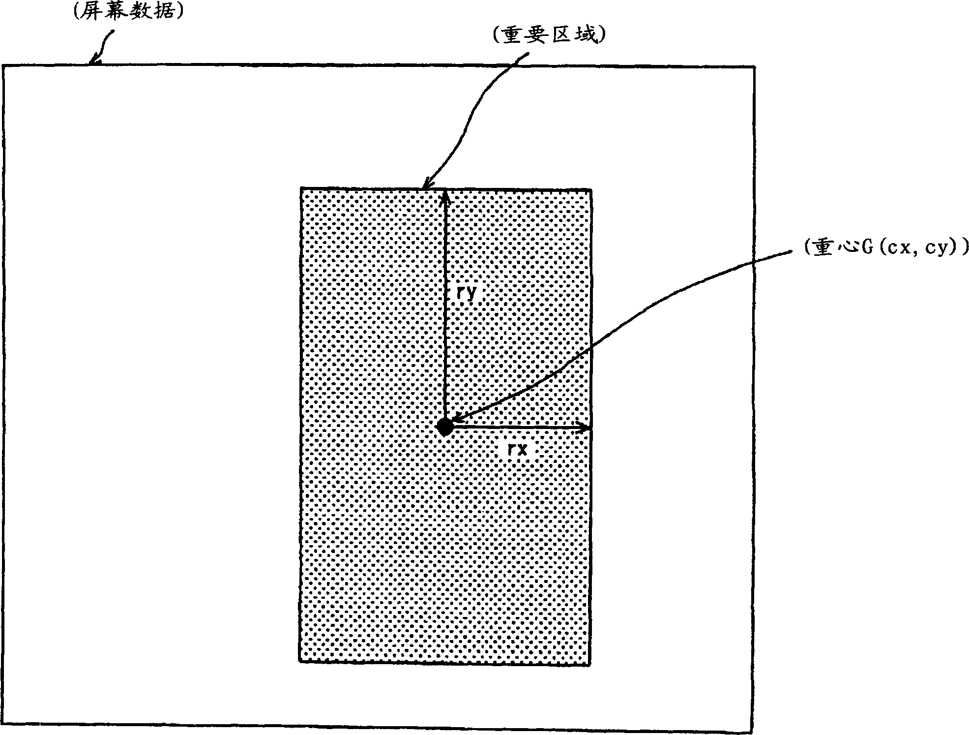
[0086] Next, a second embodiment of the video coding apparatus according to the present invention will be described. Since the structure of the video encoding device according to this embodiment is the same as figure 1 The first embodiment shown is the same, therefore, the description of the structure of each part having the same structure is omitted, and the drawings used in the first embodiment are referred to. The video encoding device 1 according to this embodiment also encodes video signals with a certain transmission bit rate, and includes: a motion compensation part 104; an important area detection part 109, which is used to automatically detect important areas in the screen; an encoding parameter calculation part 110 , used to calculate the image update rate corresponding to the degree of reliability representing detection accuracy.

[0087] Next, this embodiment will be described. In this embodiment, operations other than those of the encoding parameter calculation...

no. 3 example

[0103] Next, a third embodiment of the video coding apparatus according to the present invention will be described. Since the structure of the video encoding device according to this embodiment is the same as figure 1 The first embodiment shown is the same, therefore, the description of the structure of each part having the same structure is omitted, and the drawings used in the first embodiment are referred to. The video encoding device 1 according to this embodiment also encodes signals at a certain transmission bit rate, and includes: a preprocessing part 103 for preprocessing an input video signal; an important area detection part 109 for automatically detecting Important area; encoding parameter calculation section 110 for calculating the strength of the pre-filter corresponding to the reliability of the preprocessing section 103 provided outside the important area, which represents the detection accuracy.

[0104] Next, the operation according to this embodiment will b...


PUM


Abstract

In order to enhance the picture quality of a detected area, the present invention provides a video coding apparatus. In the apparatus, a reliability indicative of the degree of coincidence of an area detected by an important area detecting section with a real important area is calculated, and a coding parameter calculating section calculates a coding parameter to be set to the detected area according to the reliability, thereby controlling the picture quality of the detected area. Consequently, a whole image has a coding bit amount which does not break the restrictions of a transmission bit rate, and a larger coding bit amount is assigned to the important area so that a picture quality thereof can be improved and a visibility can be enhanced. In addition, the picture quality is more enhanced if a probability that the detected area might be an important area is higher.

Description

technical field [0001] The invention relates to a video encoding device for encoding a video signal with a transmission bit rate limited according to encoding parameters. Background technique [0002] In recent years, due to the development of communication technology and the improvement of infrastructure, video signals can be sent and received through transmission paths and stored in storage media. In general, video signals have a large amount of information. Therefore, in the case where a video signal is to be transmitted using a transmission path with a limited transmission bit rate or stored in a storage medium with a limited storage capacity, a method for compressing and encoding the video signal is indispensable. technology. As one of the methods for compressing and encoding video signals, a standard MPEG (Moving Picture Experts Group) has been proposed by ISO / IEC, which is a method for reducing redundancy by using the temporal correlation and spatial correlation of ...

Claims


Application Information

Patent Timeline
Patent Type & Authority Applications(China)
IPC IPC(8): H04N19/00H03M7/30H04N19/117H04N19/126H04N19/132H04N19/134H04N19/167H04N19/172H04N19/196H04N19/503H04N19/51H04N19/587H04N19/61H04N19/625H04N19/80H04N19/85H04N19/91
CPCH04N19/00781H04N19/00751H04N19/002H04N19/00193H04N19/00127H04N19/0026H04N19/00066H04N19/0009H04N19/587H04N19/117H04N19/124H04N19/132H04N19/152H04N19/154H04N19/17H04N19/61
Inventor 本田义雅上野山努
Owner PANASONIC CORP
Why Eureka
Try Eureka