Positioning servocontroller

A technology of servo controller and control part, applied in the direction of digital control, program control, electrical program control, etc., to achieve the effect of simplifying gain adjustment

Inactive Publication Date: 2003-07-09
YASKAWA DENKI KK
View PDF0 Cites 23 Cited by
  • Summary
  • Abstract
  • Description
  • Claims
  • Application Information

AI Technical Summary

Problems solved by technology

[0087] the above Figure 37 A problem with existing positioning servo controllers is that it is difficult to easily achieve the required response characteristics in the case of disturbance response adjustments, even when the adjustment gain is used to adjust the gain of the feedback control system using one parameter

Method used


Image

  • Positioning servocontroller
  • Positioning servocontroller
  • Positioning servocontroller

Examples


no. 1 example

[0149] First, refer to Figure 1 to Figure 4 , the positioning servo controller according to the first embodiment of the present invention which achieves the first object will be described.

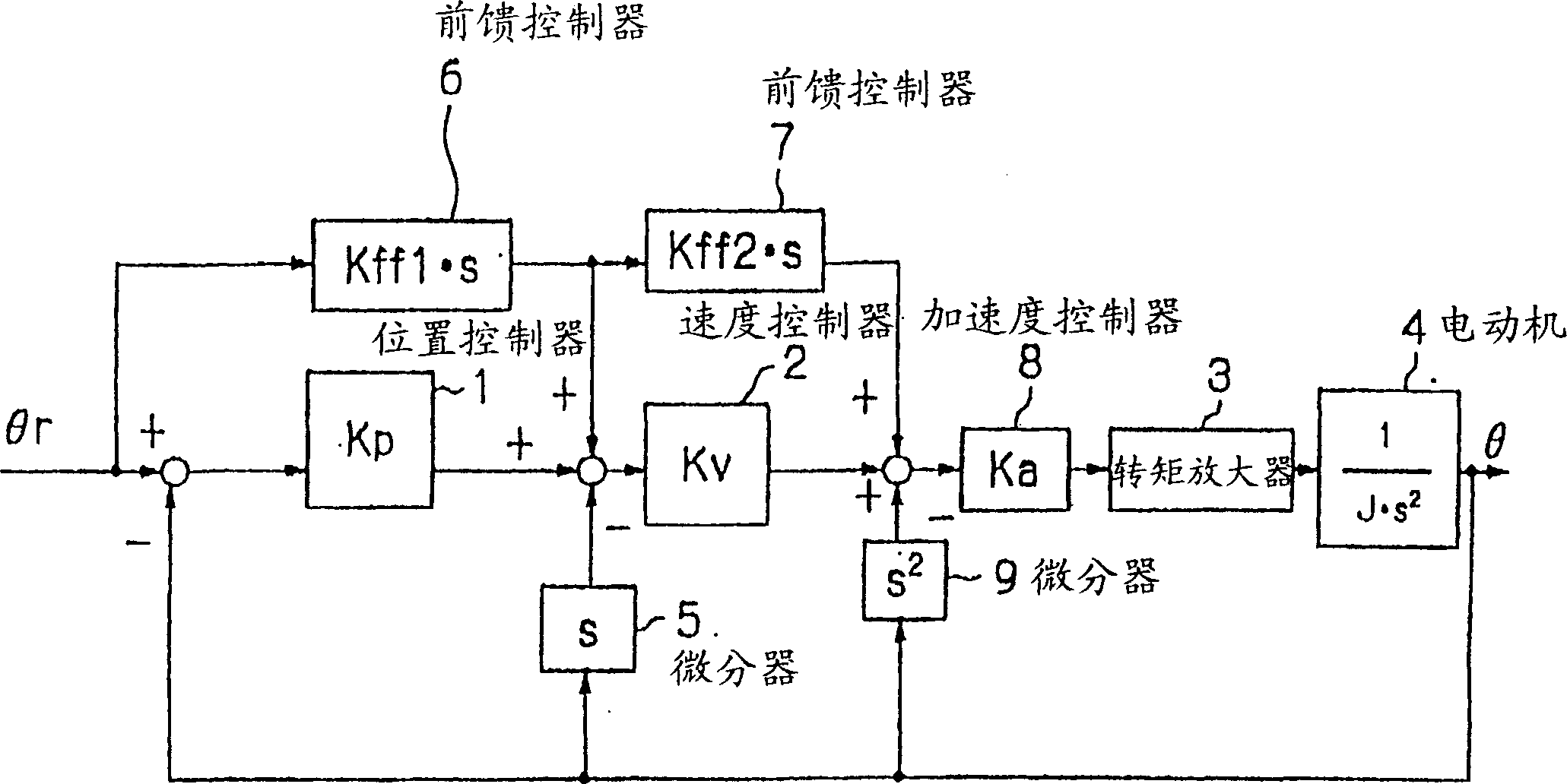
[0150] figure 1 is a control block diagram showing the configuration of a positioning servo controller of one embodiment. The positioning servo controller of this embodiment and Figure 32 The difference of the existing positioning servo controller is that the controller includes an acceleration controller 8 and a differentiator 9 .

[0151] The differentiator 9 takes the second-order differential of the position response θ of the motor 4 to output the acceleration of the motor 4 . The acceleration controller 8 is a proportional controller that receives an acceleration deviation, that is, a value obtained by adding the value output from the speed controller 2 and the value output from the feedforward controller 7, and the value obtained from the differentiator 9 outputs the accelerat...

Embodiment 2-1

[0174] Figure 5 It is a block diagram showing the configuration of the positioning servo controller of the embodiment 2-1.

[0175] exist Figure 5 in, with Figure 6 Components that are the same as those are denoted by the same reference numerals, and thus descriptions thereof are omitted.

[0176] The positioning servo controller of this embodiment is constituted as, in Figure 6 In the shown conventional positioning servo controller, amplifiers 101 and 102 are respectively provided behind the position controller 1 and the speed controller 2 .

[0177] Amplifier 101 multiplies the value output from position controller 1 by adjustment gain Kg, and outputs the resultant value as speed command ωr. Amplifier 102 multiplies the value output from speed controller 2 by adjustment gain Kg, and outputs the resultant value as torque command Tr.

[0178] To make the description simple and clear, in this embodiment, as in the prior art embodiment, it is assumed that the controlled...

Embodiment 2-2

[0198] The positioning servo controller of Embodiment 2-2 will be described below.

[0199] Figure 8 is a block diagram showing the configuration of the positioning servo controller according to the second embodiment of the present invention.

[0200] In the positioning servo controller of this embodiment, the present invention is applied to a positioning servo controller in which the position is controlled by P (proportional) control and the speed is controlled by P-I (proportional-integral) to control.

[0201] The positioning servo controller of this embodiment is constituted as, in Figure 5 The positioning servo controller of the first embodiment shown is also provided with an integrator 16 and an amplifier 103 .

[0202] The integrator 16 integrates the speed deviation between the speed command ωr and the speed ω of the motor 4, and outputs a value obtained by multiplying the integral result by an integral gain Ki. Amplifier 103 multiplies the value output from inte...


PUM


Abstract

A positioning servocontroller performs optimum positioning simply by adjusting control gain. A positioning servocontroller comprises speed feedforward control means (22) that uses a speed command corresponding to the sum of a position deviation and a first feedforward compensation; acceleration feedforward means (23) that uses an acceleration command corresponding to the sum of a speed deviation and a second feedforward compensation obtained by amplifying and differentiating the first feedforward compensation amount; and a torque amplifier (3) that drives an object based on an acceleration deviation as a torque command. The first feedforward gain and the second feedforward gain are derived from a function that uses the values of control gain as arguments.

Description

technical field [0001] The invention relates to a positioning servo controller (position control device) for positioning a controlled object, in particular to a positioning servo controller for positioning a motor. Background technique [0002] Figure 30 It is a control block diagram showing the configuration of a conventional positioning servo controller. Such as Figure 30 As shown, the existing positioning servo controller consists of a position controller 1 , a speed controller 2 , a torque amplifier 3 , a motor 4 and a differentiator 5 . [0003] The inertia of the positioning servo controller is J[N m s 2 ] The position θ[rad] of the motor 4 is controlled. [0004] The motor 4 is provided with an encoder (not shown), so that the position θ of the motor 4 can be detected by the encoder. A position deviation (θr−θ) between a position command θr supplied from a high-level unit (not shown) and the position θ of the motor 4 is input to the position controller 1 . [00...

Claims


Application Information

Patent Timeline
Patent Type & Authority Applications(China)
IPC IPC(8): G05B19/19G05D3/12
CPCG05B19/19G05B2219/41012
Inventor 富田浩治
Owner YASKAWA DENKI KK
Why Eureka
Try Eureka