Electrostatic driver

A technology of electrostatic drive and driver, which is applied in the direction of fast-moving devices, electrostatic motors, electrostatic generators/motors, etc.

Inactive Publication Date: 2003-07-30
TAIWAN SEMICON MFG CO LTD
View PDF1 Cites 6 Cited by
  • Summary
  • Abstract
  • Description
  • Claims
  • Application Information

AI Technical Summary

Problems solved by technology

Some systems are difficult to control because they are not des

Method used


Image

  • Electrostatic driver
  • Electrostatic driver
  • Electrostatic driver

Examples


Embodiment Construction

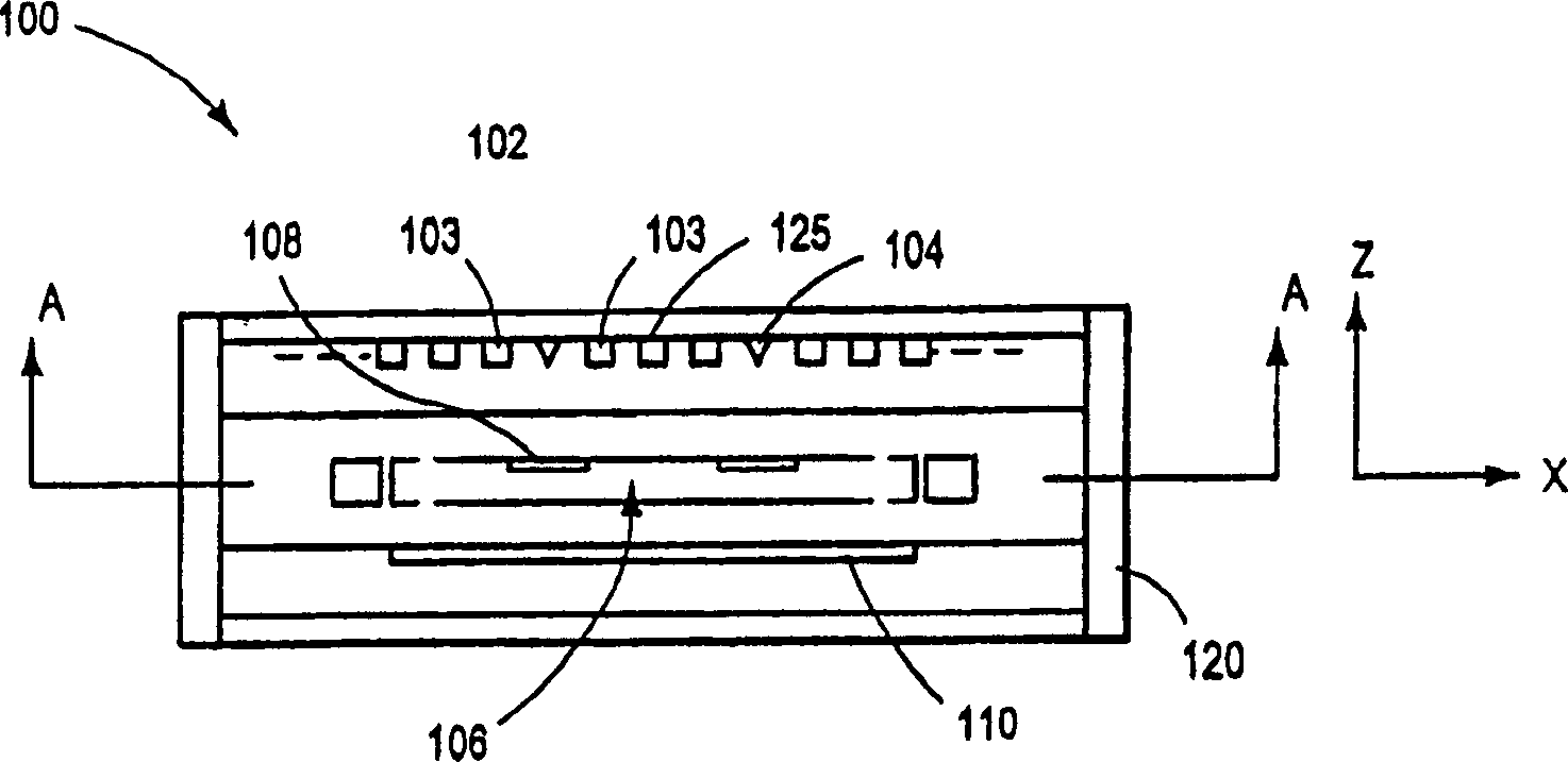
[0010] The present invention is directed to electrostatic driving devices. The electrostatic drive device embodiments described here can be used in a variety of devices, but have proven to be particularly beneficial for use in very small computer storage devices and other MEMS systems. For illustrative purposes only, the following embodiments of the electrostatic drive device will be discussed mainly in the context of high-density MEMS computer storage devices.

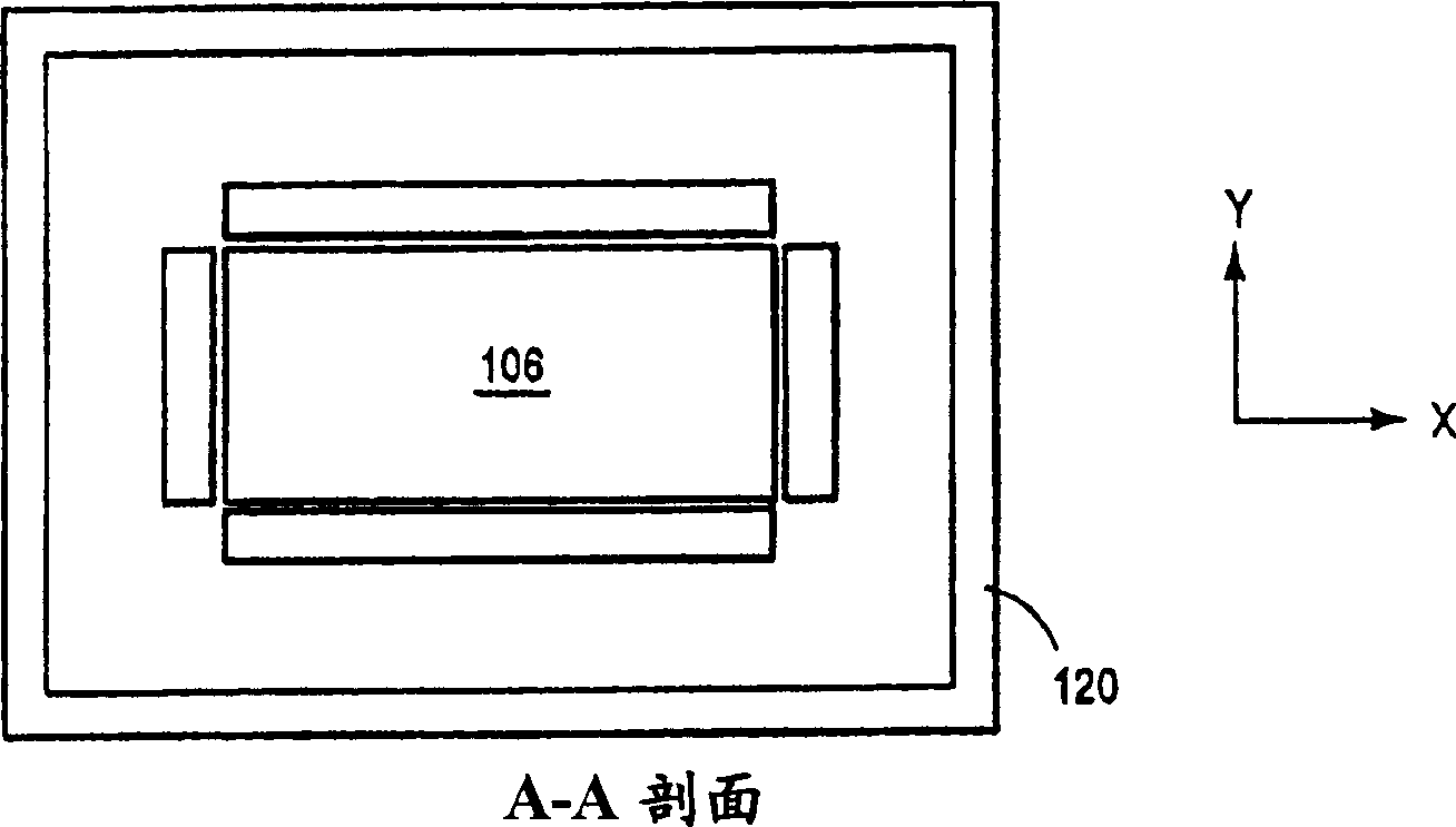
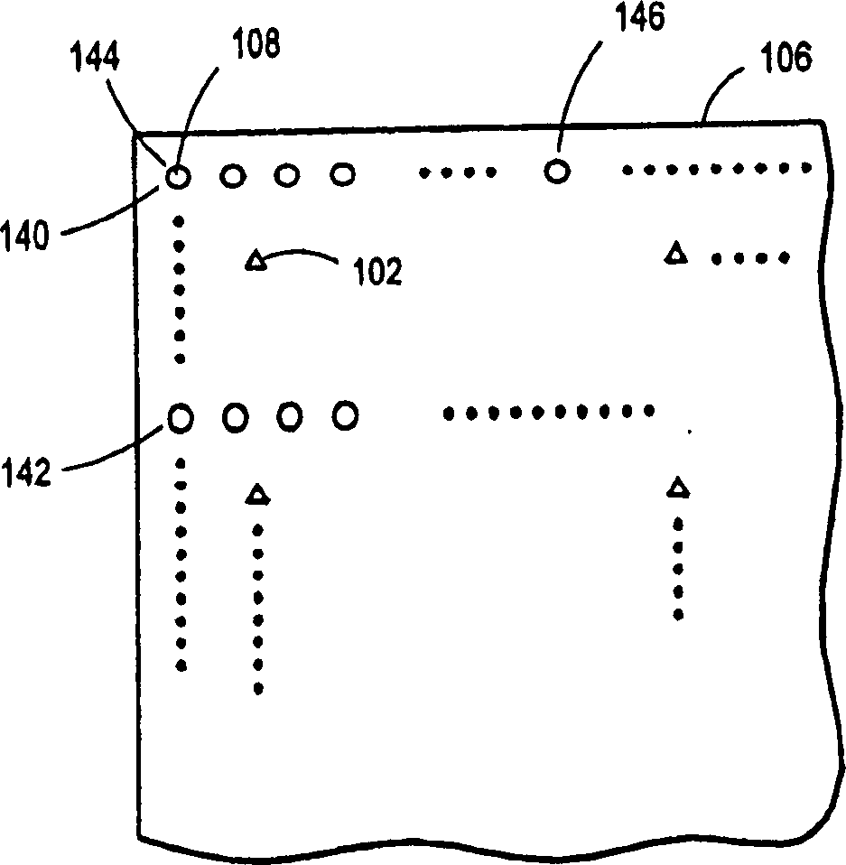
[0011] figure 1 with figure 2 The side and top cross-sectional views of the storage device 100 are respectively illustrated, in which the electrostatic drive device according to the present invention can be used. The storage device 100 includes: several field emitters, such as 102 and 104; a storage medium 106 with several storage areas such as 108; and a microactuator 110, which makes the storage medium 106 relative to the field Cause the emitter to scan (move) or vice versa. The storage device 100 may be configured s...


PUM


Abstract

An electrostatic drive 150 having a plurality of mover electrodes 152 operatively secured to a mover 154, and a plurality of stator electrodes 156 operatively secured to a stator 158. The mover 154 and stator 158 are configured to move relative to each other via electrostatic force generated between the mover electrodes 152 and the stator electrodes 156. The electrostatic drive 160 includes a driver configured to place the stator electrodes 158 in any of a number of sequential voltage states, each being defined by a combination of LO and HI voltage levels at the individual stator electrodes 156. Transition from one voltage state to a sequentially adjacent voltage state produces a step size of relative movement between the mover 154 and stator 158. For each of the sequential voltage states, the driver 160 is further configured to selectively vary voltage applied at one of the stator electrodes 156 to an amount between the LO and the HI voltage levels, in order to produce a proportionally smaller step size.

Description

Technical field [0001] The present invention relates to an electrostatic drive device in which the voltage of one or more electrodes is controlled to generate electrostatic force, which causes relative movement between two or more objects on which the electrodes are fixed. Background technique [0002] It has been known to use electrostatic force to control the movement between a pair of objects. One way to achieve this control is to fix or form electrodes on a pair of objects, and then apply voltage to the electrodes to generate electrostatic force. By considering the details of the physical connection between objects, the voltage and the generated electrostatic force can be cleverly controlled to control the movement between objects. [0003] In micro-electromechanical systems (MEMS), it is often necessary to achieve very small and fine motions in a certain range of motion between objects. For this reason, sometimes a large number of electrodes are used, the electrodes are very...

Claims


Application Information

Patent Timeline
IPC IPC(8): B81B5/00B81B7/02G11B9/10H01J21/08H02N1/00
CPCH02N1/004G11B7/00
Inventor D·J·法森
Owner TAIWAN SEMICON MFG CO LTD
Why Eureka
Try Eureka