
Apparatus and method to improve resolution of infrared touch systems

An infrared touch and touch screen technology, applied in the input/output process of data processing, instruments, mechanical mode conversion, etc.

Inactive Publication Date: 2003-07-30
ELO TOUCH SOLUTIONS INC
View PDF0 Cites 33 Cited by
  • Summary
  • Abstract
  • Description
  • Claims
  • Application Information

AI Technical Summary

Problems solved by technology

There is currently no such system or method, but if there were, it would greatly increase the capabilities and usability of infrared touch screen systems

Method used


Image

  • Apparatus and method to improve resolution of infrared touch systems
  • Apparatus and method to improve resolution of infrared touch systems
  • Apparatus and method to improve resolution of infrared touch systems

Examples


Embodiment Construction

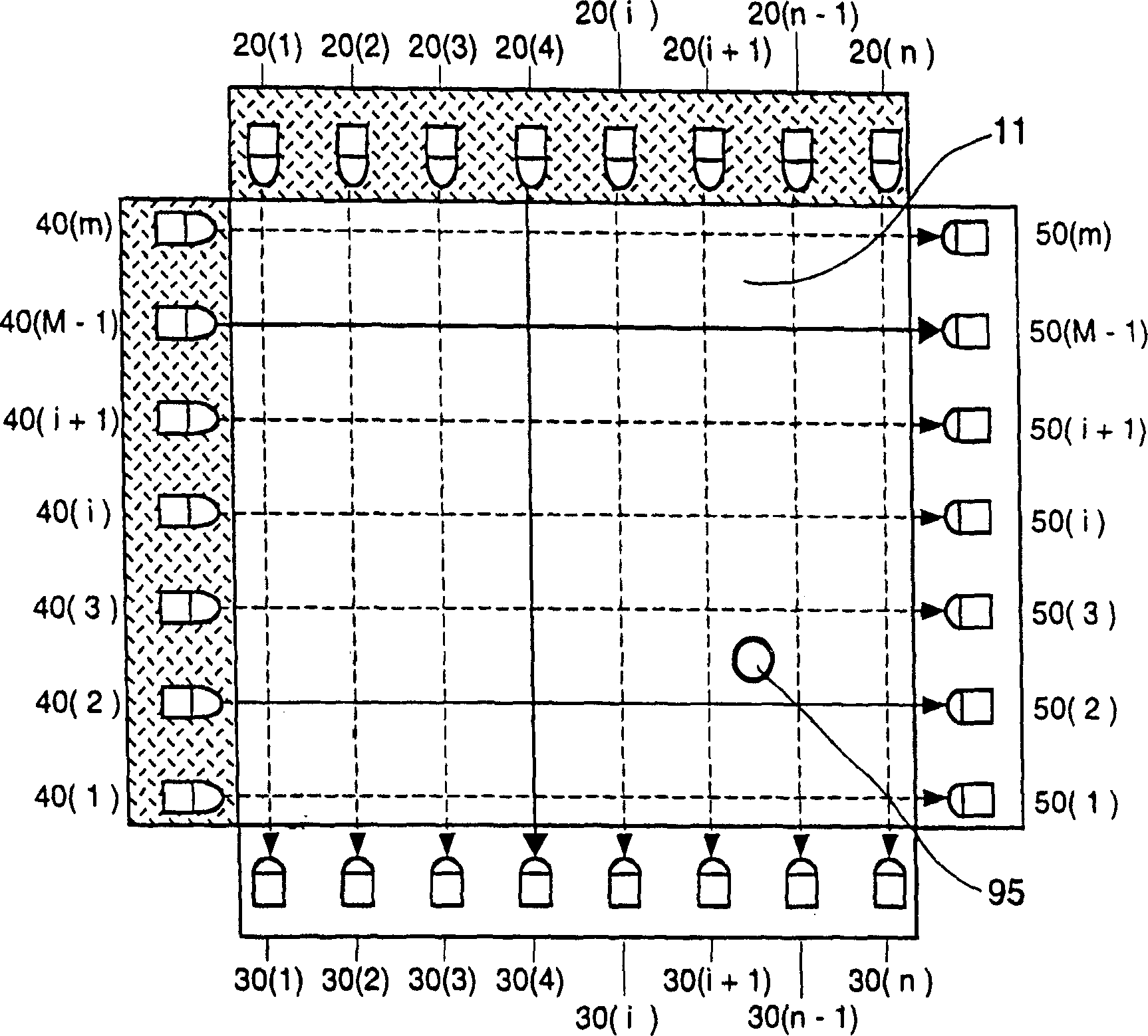
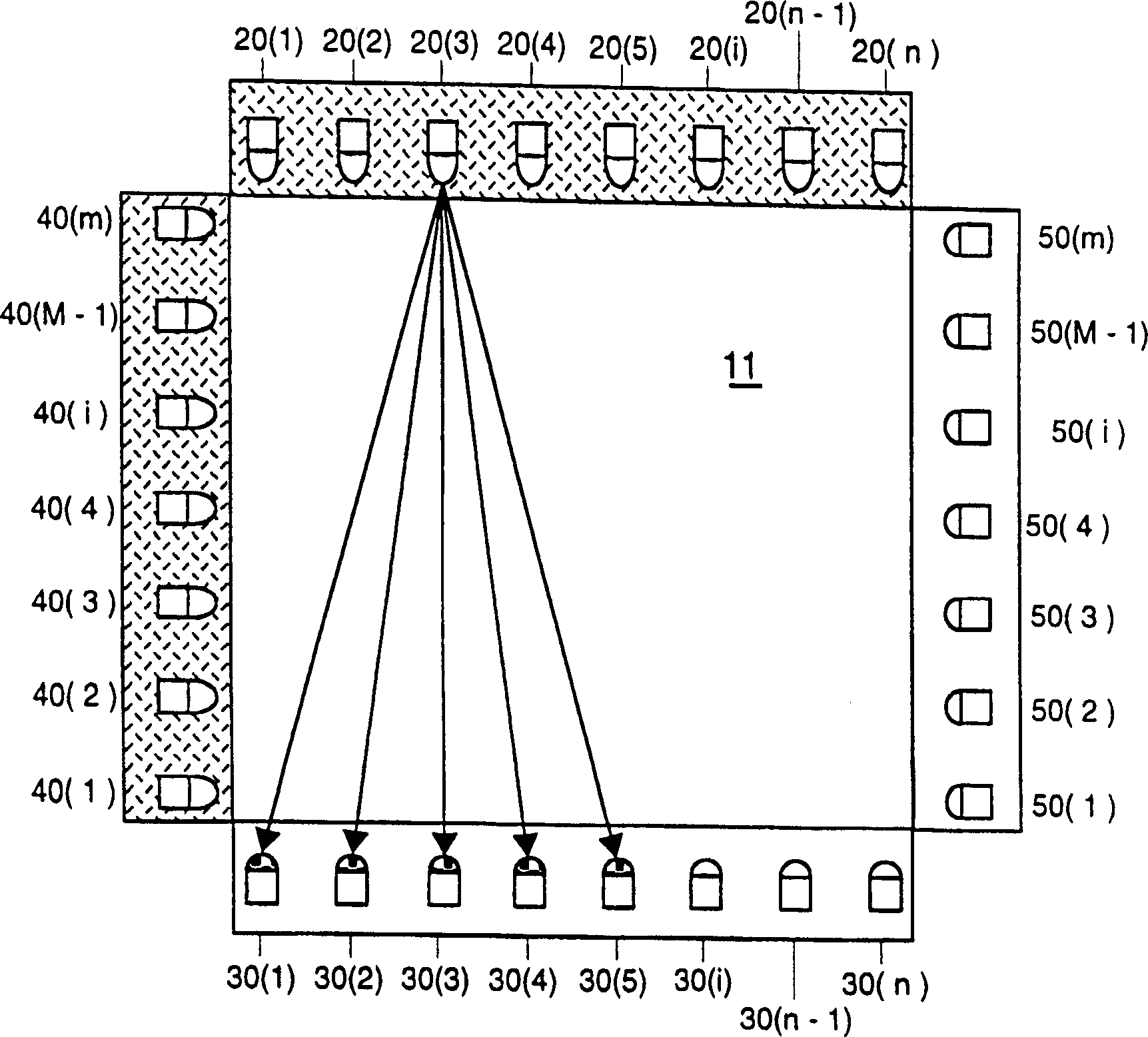
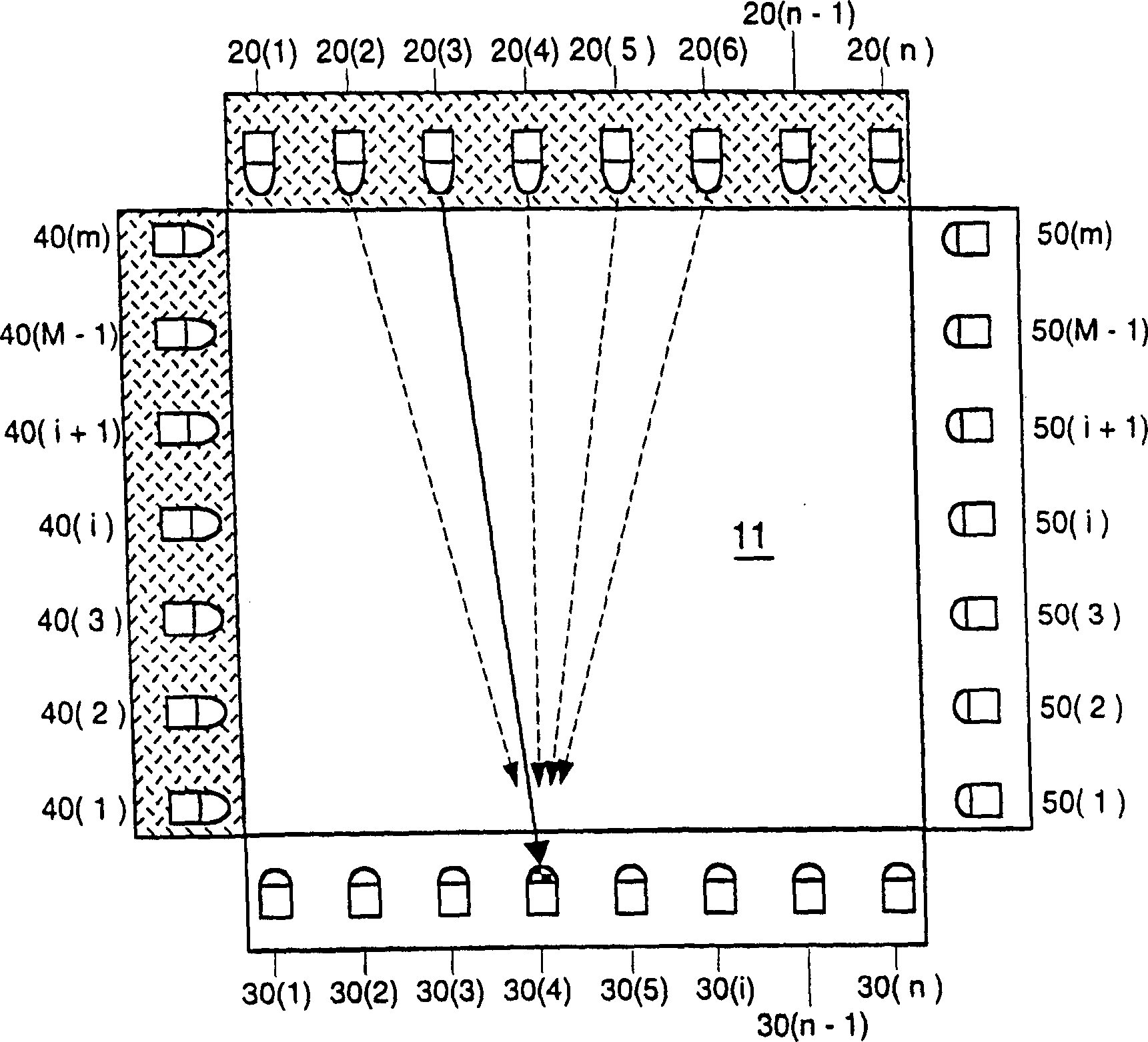
[0028] The present invention is directed to an infrared ("IR") touch system that utilizes on-axis and off-axis detection to increase the resolution of the touch location of the touch system. The present invention also provides a method for determining the on-axis and off-axis detection of a touch system using the multiple steps of rough scanning an infrared emitter-receiver pair and fine scanning a selected emitter-receiver pair. the touch location. The present invention also takes advantage of the fact that, for a given x and y touch location, the selection of other transmitter-receiver pairs to determine the exact touch location depends on the touch location. In other words, the selection of a y-coordinate transmitter-receiver pair for precise determination of x-position can be determined from the x-coarse position, and an x-coordinate transmitter-receiver pair can be determined from the y-coarse position.

[0029] As mentioned above, as shown in FIG. 1 , a traditional touc...


PUM


Abstract

A touch system using a plurality of infrared ('IR') transmitters and receivers, and a method of determining with increased resolution the location of a touch between the IR transmitters and receivers using on-axis and off-axis detection are disclosed. The inventive touch system and method use, in conjunction with the on-axis and off-axis detection, a coarse and fine sweep of the transmitters and receivers to increase the resolution of identified touch location. The method of determining a touch location involves selection and activation of particular off-axis infrared transmitter and receiver pairs determined from a triangulation interdependence between the x and y coordinates. The increased resolution of the identified touch location is achievable using the inventive system and method without the need for an increased number of IR transmitters and receivers and without the need for higher speed processing capability.

Description

field of invention [0001] Generally, the present invention relates to infrared ("IR") touch systems or touch screens. Specifically, the object of the present invention is to provide a system and method for improving the resolution of an infrared touch system. Such systems and methods utilize on-axis and off-axis infrared emitter-receiver detection to determine touch locations on the screen with higher resolution. In one embodiment of the method of the present invention, the touch location is determined in multiple steps, first determining a rough touch location and then determining the precise location of the touch within the coarse location area. Utilizing the systems and methods of the present invention enables increased touch location resolution without increasing the density of infrared emitters and receivers, or increasing processor speed. Background of the invention [0002] Touching the system occurs more and more often in daily activities. Miniaturized touch syste...

Claims


Application Information

Patent Timeline
IPC IPC(8): G06F3/042G06F3/033H01H36/00
CPCG06F3/0421
Inventor T·E·马斯特斯R·W·克内特施H·A·小格里斯J·迪肯
Owner ELO TOUCH SOLUTIONS INC
Learn More