Loom take-up motion

A technology of looms and cloth rolls, used in looms, textiles, winding strips, etc.

Inactive Publication Date: 2003-08-06
TSUDAKOMA KOGYO KK
View PDF0 Cites 20 Cited by
  • Summary
  • Abstract
  • Description
  • Claims
  • Application Information

AI Technical Summary

Problems solved by technology

[0003] In the above technology, since the cloth rolling roller rotates but the pressure roller does not rotate, the fabric around the pressure roller tends to sway due

Method used


Image

  • Loom take-up motion
  • Loom take-up motion
  • Loom take-up motion

Examples


Embodiment Construction

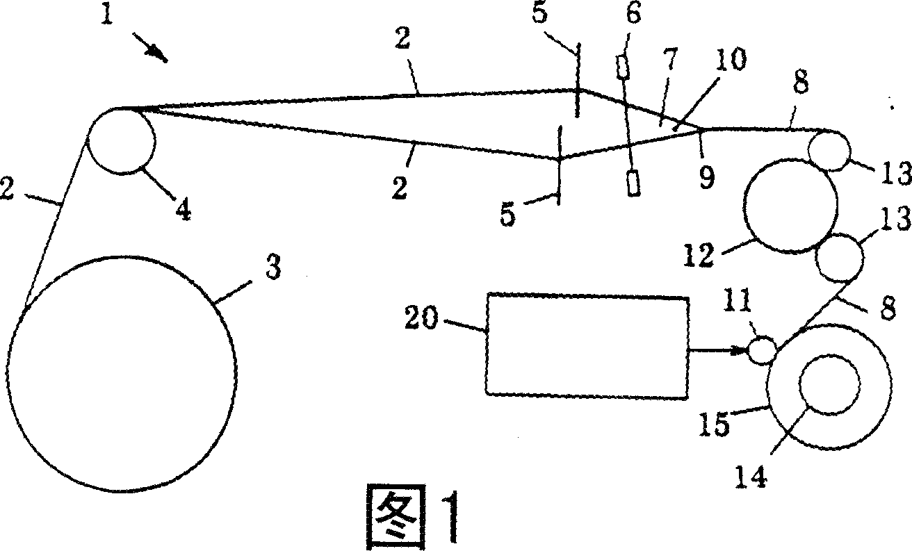
[0020] FIG. 1 shows the main part structure of a general loom 1 . In this FIG. 1 , the warp 2 is sent out in sheet form from the warp bundle 3 , passes through the support roller 4 and penetrates the heddle 5 and the reed 6 , forms an opening 7 and reaches the cloth fell 9 of the fabric 8 at the same time. On the other hand, after the weft thread 10 is weaved into the opening 7 of the upper and lower warp threads 2 and beats up, it is beaten into the cloth fell 9 of the fabric 8 by the reed 6 to form the fabric 8 . One side of the fabric 8 passes through the pressure roller 13, the floating yarn take-up roller 12, and the other side passes through the pressure roller 13 and the pressure roller 11 of the pressing part, and is wound into a cloth roll 15 on the outer circumference of the cloth winding roller 14.

[0021] Moreover, the cloth roll 11 as a crimping member is extended in the width direction of the cloth roll 14, and is displaced according to the increase of the roll ...


PUM


Abstract

The present invention provides a loom take-up motion (20) comprises a pressing member (pressure roller) (11) with its axis extended in parallel to that of a take-up roller (14) and pressed against a fabric roll (15) of a fabric (8) wound on the take-up roller (14), a variable-speed driving device (16) for driving the pressing member (11) for rotation about the axis thereof in a fabric winding direction, and a take-up controller(17) capable of controlling the driving device (16) by giving a speed signal produced on the basis of take-up speed at which the fabric (8) is wound round the take-up roller (14) to the driving device (16) to control the surface speed of the pressing member (11) properly according to weaving conditions including the type of the fabric (8) and the diameter of the fabric roll (15). The pressing member (11) is rotated positively while the fabric (8) is being wound round the take-up roller (14) to prevent forming folds and creases in the fabric(8) in the fabric roll (15).

Description

technical field [0001] The present invention relates to a fabric winding device of a loom, which press-contacts a crimping member to a cloth roll of fabric wound on a cloth winding roller, and controls the peripheral speed of the crimping member to be appropriate. Background technique [0002] In order to prevent wrinkling, Publication No. 52-21807 maintains a cylindrical part larger than the width of the fabric in a crimpable state on the fabric roll wound on the fabric roll (take-up roll). roll). The pressure of the pressure roller is obtained by the self-weight of the pressure roller or the elastic force of an additional spring or the like. Therefore, the fabric is wound on the cloth roller after passing through the doctor blade between the cloth roller and the pressure roller. [0003] In the above technology, since the cloth rolling roller rotates but the pressure roller does not rotate, the fabric around the pressure roller tends to sway due to the pressing effect of...

Claims


Application Information

Patent Timeline
IPC IPC(8): B65H18/10B65H18/26D03D49/20
CPCB65H2701/174B65H18/26B65H18/10B65H2511/135D03D49/20B65H2404/434B65H2515/12B65H2513/104B65H2513/10B65H2220/01B65H2220/02
Inventor 浦垣裕角谷和人
Owner TSUDAKOMA KOGYO KK
Why Eureka
Try Eureka