Method for mfg. intake manifold for electric injection engine

A technology of intake manifold and processing method, which is applied in the direction of engine components, machines/engines, mechanical equipment, etc., can solve the problems of large volume, high cost per piece, and large equipment investment.

Inactive Publication Date: 2003-08-13
哈尔滨志阳汽车电气股份有限公司
View PDF0 Cites 1 Cited by
  • Summary
  • Abstract
  • Description
  • Claims
  • Application Information

AI Technical Summary

Problems solved by technology

At present, there are mainly two common methods for manufacturing engine intake manifolds: one uses conventional pressure casting, which has the characteristics of simple casting process and mature technology, but its processing quality is poor and its volume is large. The u

Method used


Image

  • Method for mfg. intake manifold for electric injection engine
  • Method for mfg. intake manifold for electric injection engine
  • Method for mfg. intake manifold for electric injection engine

Examples


Embodiment Construction

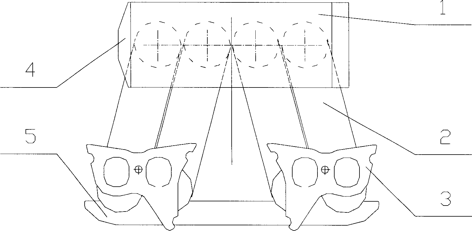
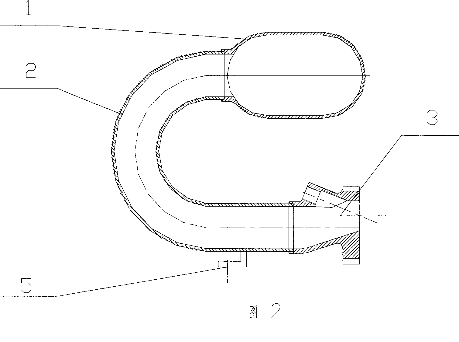
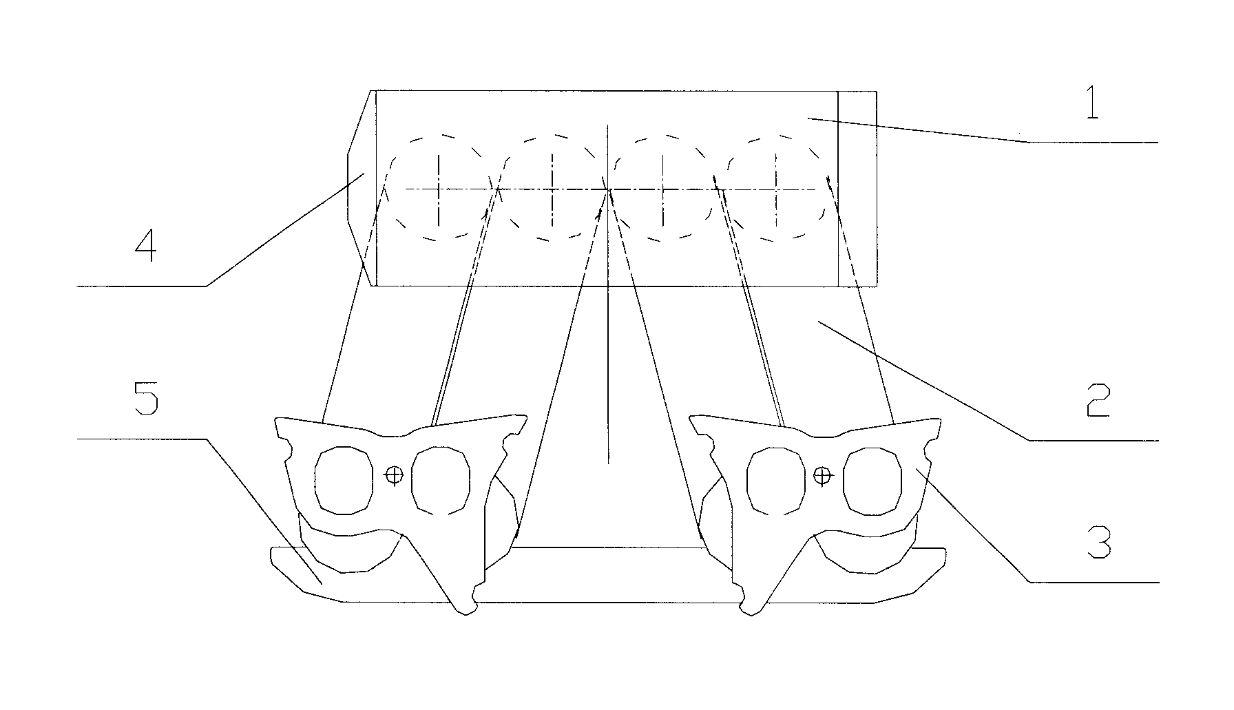
[0013] Depend on figure 1 --- As shown in Fig. 2, the present invention is

[0014] a. After the intake manifold is cut and blanked, it is bent and formed by a CNC pipe bender with a bending angle of 180 degrees.

[0015] b. After the metal sheet is blanked, it is extruded into a cylindrical shape with a mold, then stretched and formed, and processed by a CNC machine tool according to the designed size to cut the blank and process it into a voltage stabilizing box.

[0016] c. The voltage stabilizing box plug is processed by precision die-casting, and then the voltage stabilizing box plug and the voltage stabilizing box body are bonded, and then the periphery of the junction between the voltage stabilizing box body and the voltage stabilizing box plug is riveted.

[0017] d. Sub-arc welding is performed between the intake manifold seat formed by precision die-casting and the inlet end of the intake manifold.

[0018] e. Weld the intake manifold frame on the outer wall of t...


PUM

PropertyMeasurementUnit
Bending angleaaaaaaaaaa

Abstract

A method for manufacturing the intake manifold of electrojet engine includes blanking tube, bending by 180 deg., blanking metal sheet, die pressing, stretching shaping, making pressure-stabilizing box, binding the block with the pressure-stabilizing box, rivetting its periphery, welding the intake manifold to its seat, and welding the holder to the intake manifold. Its advantages are simple technology, good sealing, smooth airflow channel and less loss of airflow.

Description

Technical field [0001] The invention relates to a processing method of an intake manifold for an electric injection engine. Background technique [0002] The intake manifold of the engine is an important component of the engine, which has a great influence on the power and output torque of the engine. At present, there are mainly two common methods for manufacturing engine intake manifolds: one uses conventional pressure casting, which has the characteristics of simple casting process and mature technology, but its processing quality is poor and its volume is large. The unit cost is relatively high. The second method is after the components are formed, the overall combination is brazed and welded. It is characterized by light weight, small size, and low unit cost, but the initial equipment investment is large and the technology is complicated. Contents of the invention [0003] The purpose of the present invention is to overcome above-mentioned weak point, provide a kind ...

Claims


Application Information

Patent Timeline
IPC IPC(8): F02M35/104
Inventor 冯恩江侯云鹳刘耀武邢树立
Owner 哈尔滨志阳汽车电气股份有限公司
Why Eureka
Try Eureka