
Ice maker heater controlling device

A control device and heater technology, which is applied in ice making, ice making, lighting and heating equipment, etc. It can solve the problems of inability to accurately control the heater, inability to remove ice normally, and inability of the temperature sensor to accurately sense the temperature of the ice making tank, etc. question

Inactive Publication Date: 2003-08-13
TAIZHOU LG ELECTRONICS REFRIGERATOR CO LTD
View PDF0 Cites 2 Cited by
  • Summary
  • Abstract
  • Description
  • Claims
  • Application Information

AI Technical Summary

Problems solved by technology

However, in the process of ending the ice removal and disconnecting the heater, the detection error of the temperature sensor cannot be ignored because the ice removal time is very short (generally about 3 minutes); if the heater is disconnected too early, it will not work normally. Ice removal; conversely, if the heater is disconnected too late, the heat generated by the heater will affect the cooling of the freezer
[0004] In a word, in the traditional ice machine, the action of the heater is controlled by using the temperature sensor to detect the temperature of the ice-making tank and following the ice-moving action. Due to the influence of the surrounding environment, the temperature sensor often cannot accurately sense the temperature of the ice-making tank. , resulting in the inability to accurately control the action of the heater

Method used


Image

  • Ice maker heater controlling device
  • Ice maker heater controlling device
  • Ice maker heater controlling device

Examples


Embodiment Construction

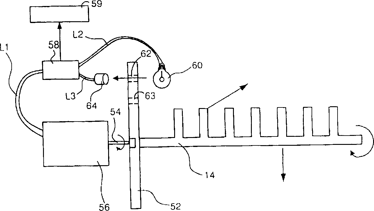
[0012] As previously mentioned, the activation of the heater 15 is carried out when the ice making process ends and the ice removal process begins, that is to say, the activation of the heater 15 means the beginning of the moving process, and the disconnection of the heater 15 means Ice removal is complete. Therefore, the control of the heater must be performed in conjunction with the ice removal process in the present invention.

[0013] Such as Figure 3a , Figure 3b As shown, the heater control device of the ice maker of the present invention is mainly composed of a light shield 52 , a light sensor and a control unit 58 . The shading plate 52 is coaxially installed on the shaft end of the rotating shaft 54 ​​of the ice-moving rod driving motor 56 with the ice-moving rod 14, so that it can be driven by the motor 56 to rotate synchronously. With the second light-transmitting hole 63, the rotation radius of the first light-transmitting hole 62 and the second light-transmit...


PUM


Abstract

A heater controller for ice maker is composed of a light shielding plate, optical sensor and controller. Said light-shielding plate and the ice moving rod are coaxially mounted to the shaft of driven motor for ice moving rod. The light-shielding plate has two light holes relative to the initial position and destination position of ice moving rod. Said optical sensor is composed of light source and light receiver. Said controller can control motor and light source, and receiving the signal from light receiver to control heater.

Description

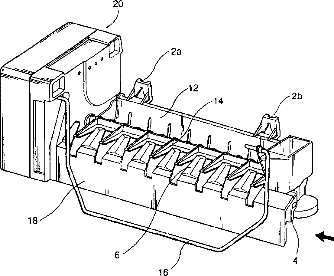
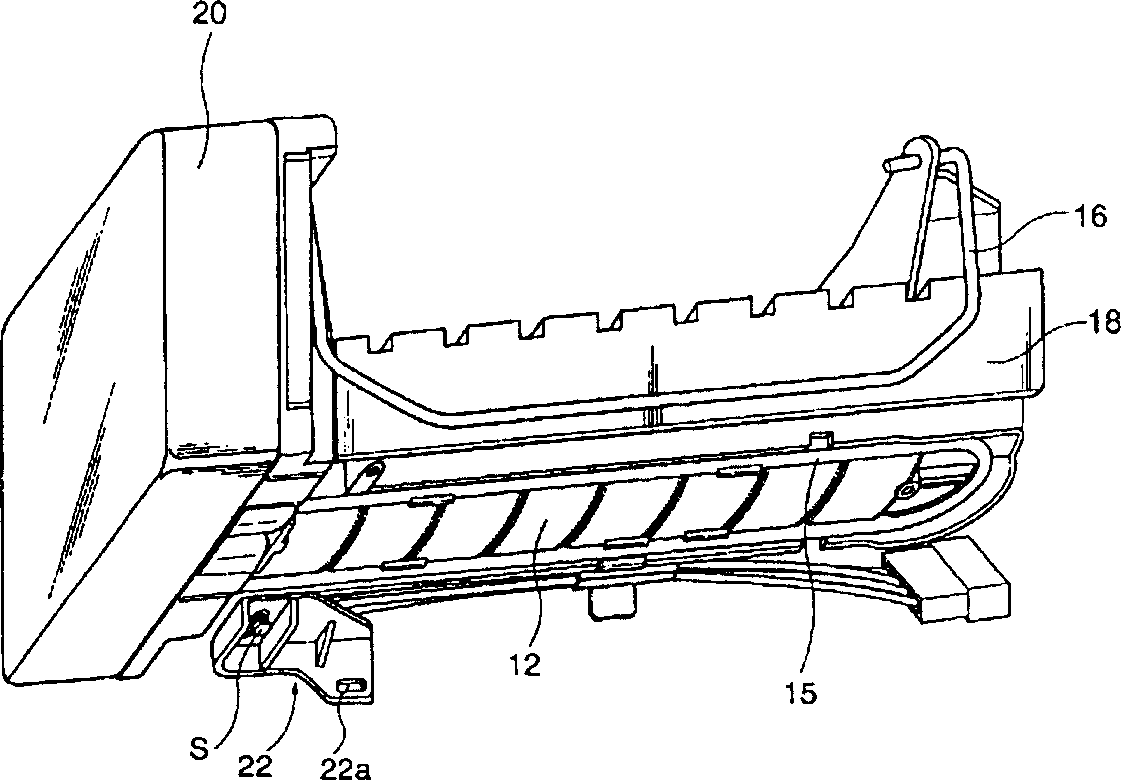
technical field [0001] The invention relates to a heater control device for an ice maker. Background technique [0002] figure 1 and figure 2 It is a schematic diagram of the structure of a general frozen ice machine. The ice maker is installed and fixed on the wall of the freezer through its upper connection cards 2a, 2b. Its ice making tank 12 is made of aluminum, and its cross-sectional shape is a half-moon shape. It is carried out by multiple water supply pipes on the side. The top of the ice-making tank 12 is provided with an ice-moving rod 14 , which is driven and rotated by a motor installed in the casing 20 to take out completely frozen ice cubes from the ice-making tank 12 . A heater 15 is provided below the ice-making tank 12. After the ice-making process is finished, the heater 15 can be started to generate a small amount of heat, so that the ice cubes close to the wall of the ice-making tank 12 are forcibly melted and separated, so as to facilitate utilizati...

Claims


Application Information

Patent Timeline
Patent Type & Authority Applications(China)
IPC IPC(8): F25C1/00
Inventor 金日信
Owner TAIZHOU LG ELECTRONICS REFRIGERATOR CO LTD
Learn More