Moving vane with trailing edge for improving thermal behaviour used for high pressure turbine

A high-pressure turbine, moving blade technology, applied in the direction of blade support elements, engine elements, machines/engines, etc., can solve problems such as unfavorable blade life

Inactive Publication Date: 2003-08-20
SNECMA MOTEURS (FR)
View PDF2 Cites 10 Cited by
  • Summary
  • Abstract
  • Description
  • Claims
  • Application Information

AI Technical Summary

Problems solved by technology

This leads to large temperature gradients at the trailing edge, which, due to conduction, lead to cracking near the connection zone, which is especially detrimental to the life of the blade

Method used


Image

  • Moving vane with trailing edge for improving thermal behaviour used for high pressure turbine
  • Moving vane with trailing edge for improving thermal behaviour used for high pressure turbine
  • Moving vane with trailing edge for improving thermal behaviour used for high pressure turbine

Examples


Embodiment Construction

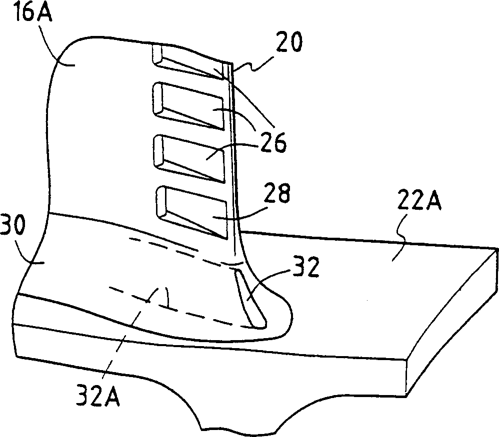
[0020] figure 1 is a perspective view of a moving blade 10 of the present invention, such as a high pressure turbine for a turbomachine. This blade has a longitudinal axis X-X and it is fixed by a generally fir-tree-shaped root 12 to the rotor disk (not shown) of the high-pressure turbine. It generally includes a base 14A, an apex 14B, a concave wall 16A, a convex wall 16B, a leading edge 18 and a trailing edge 20 . The root 12 is connected to the blade base 14A at a platform 22 which forms the inner wall for the gas flow through the high pressure turbine.

[0021] The blades are subjected to very hot gases and therefore require cooling. For this purpose, in known manner, the moving blade 10 has at least one internal cooling circuit, for example formed by at least one internal cavity 24 extending radially between the blade base 14A and the tip 14B. The cavity is fed with cooling air via one of its radial ends through an air inlet (not shown). The air inlet is usually loca...


PUM


Abstract

The blade (10) has at least one cavity (24) radially extending between its tip and its base to form at least one cooling circuit. Air is discharged from the cavity through exhaust slots (26) opened to the blade trailing edge (20). A connection zone (30) is formed between the blade base and the platform (22) top surface. An auxiliary exhaust slot leads air from the cavity to the discharge side of the zone. An Independent claim is also included for a high-pressure turbine.

Description

technical field [0001] The present invention relates to the field of moving blades for high-pressure turbines of turbomachines, in particular to slots for discharging cooling air from moving blades of high-pressure turbines. Background technique [0002] Typically, a turbine has a combustion chamber where air and fuel are mixed prior to combustion. The combustion gases flow downstream in the combustion chamber and are fed to the high-pressure turbine. The high pressure turbine has one or more rows of moving blades spaced circumferentially about the turbine rotor. The moving blades of the high-pressure turbine are exposed to very hot gases. These temperatures reach values ​​far beyond what the blades exposed to the gas can withstand without damage, with a limited lifetime as a result. [0003] In order to solve this problem, it is known that such blades can be provided with an internal cooling circuit for reducing the temperature. With this circuit, the cooling air, usual...

Claims


Application Information

Patent Timeline
Patent Type & Authority Applications(China)
IPC IPC(8): F01D5/18
CPCF05D2240/81F01D5/186F01D5/187F05B2240/801
Inventor 雅克·布里莫里斯·朱代雅基·塔巴丁
Owner SNECMA MOTEURS (FR)
Why Eureka
Try Eureka