Optical fiber

A technology of optical fiber and fiber core, applied in cladding optical fiber, optics, light guide, etc., to achieve the effect of low loss characteristics, high-speed and high-quality optical data transmission

Inactive Publication Date: 2003-08-27
FUJIKURA LTD
View PDF0 Cites 6 Cited by
  • Summary
  • Abstract
  • Description
  • Claims
  • Application Information

AI Technical Summary

Problems solved by technology

This high transmission loss in optical fiber is caused by Rayleigh loss

Method used


Image

  • Optical fiber
  • Optical fiber
  • Optical fiber

Examples


no. 1 approach

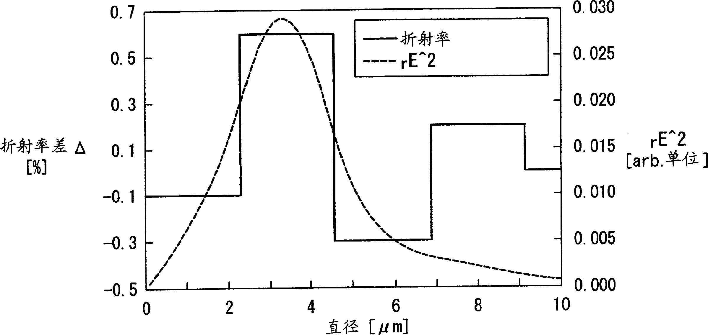
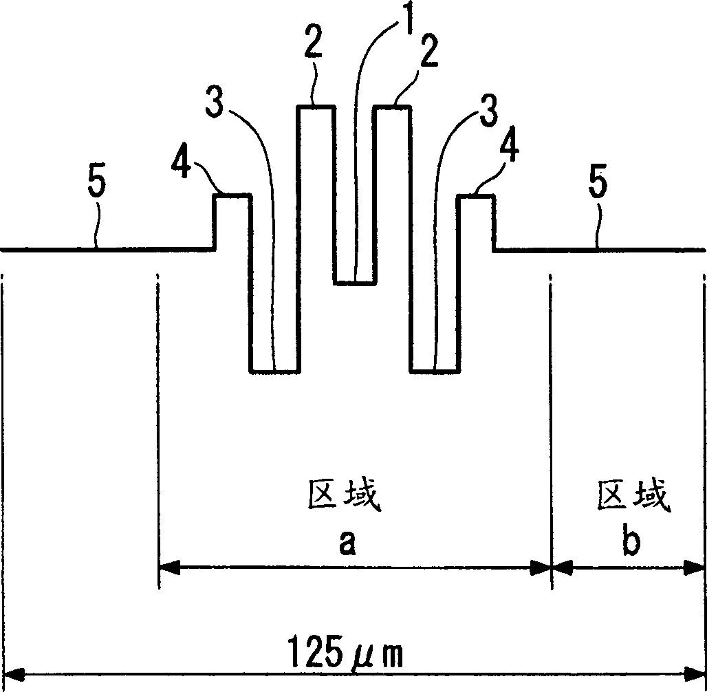
[0067] has produced a figure 1 Fiber with refractive index profile shown. This optical fiber is manufactured by using chemical vapor deposition (hereinafter referred to as CVD) method to produce figure 2 The region (a) in the optical fiber with the shown refractive index profile, this region (a) contains the core; figure 2 The region (b) in the fiber of the shown refractive index profile, this region (b) contains the cladding. attached here figure 2 As shown, the outer diameter of the fiber cladding is 125 μm. The chromatic dispersion at the wavelength of 1550nm in this fiber is +8ps / nm / km, which meets the requirements of product design. The properties of this fiber are shown in Table 2.

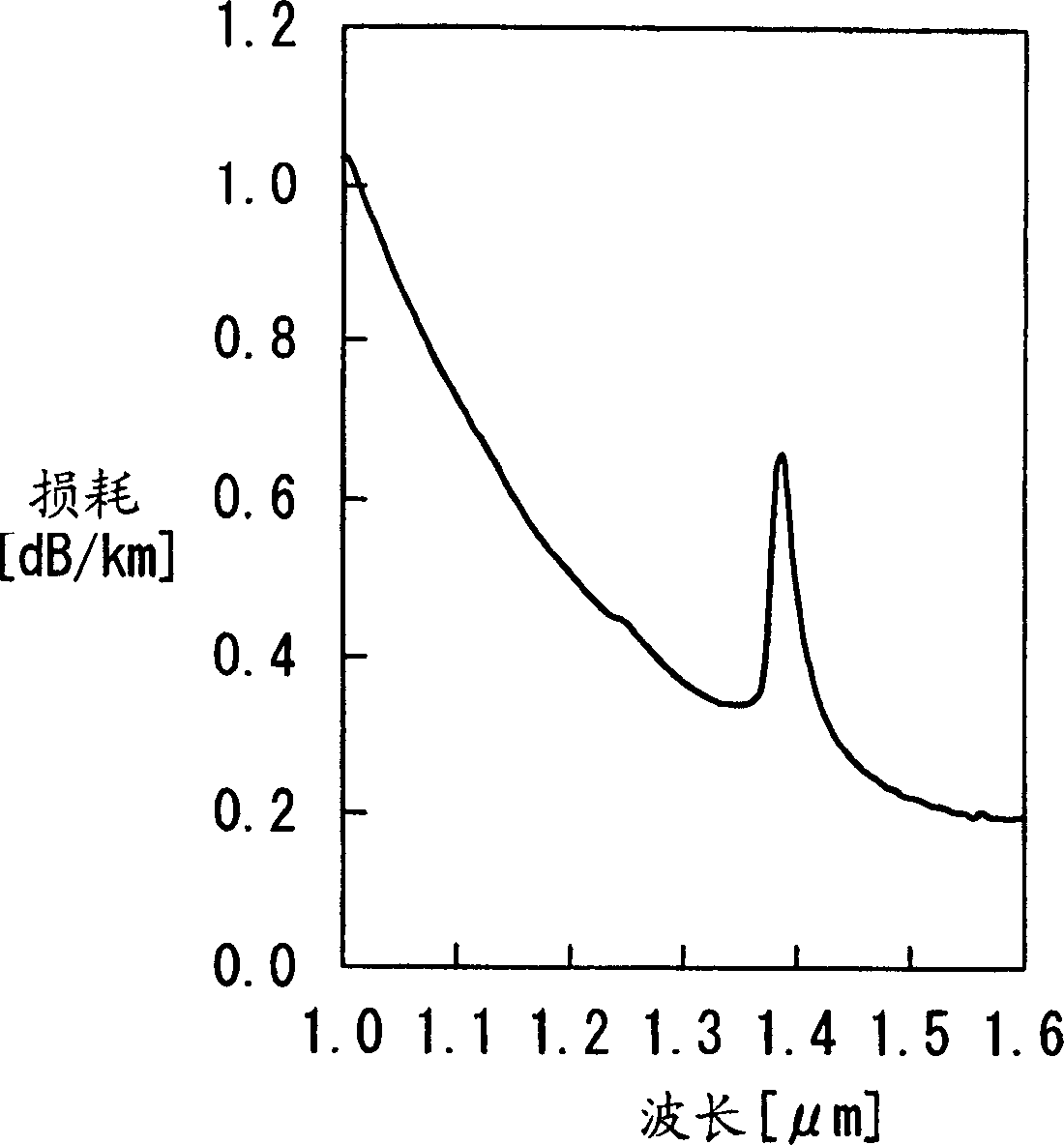
[0068] transmission loss

[dB / km]

0.206

Cable cut-off wavelength λcc

[nm]

1450

Effective core cross-sectional area A eff

[μm 2 ]

100.6

Mode Field Diameter MFD

[μm]

9.26

Dispersion

[ps / nm / km]

8.0

...

no. 2 approach

[0074] has produced a Figure 5 , 6 Fiber with refractive index profile shown.

[0075] attached Figure 5 Design values ​​of the refractive index profile in the general NZ-DSF dispersion region are shown. attached Image 6Design values ​​of the refractive index distribution are shown when the dispersion is set to about +9 ps / nm / km higher than the dispersion of the ordinary NZ-DSF. This optical fiber is manufactured by using chemical vapor deposition (hereinafter referred to as CVD) method to produce figure 2 The region (a) in the optical fiber with the shown refractive index profile, this region (a) contains the core; figure 2 The region (b) in the fiber of the shown refractive index profile, this region (b) contains the cladding. attached here figure 2 As shown in , the outer diameter of the cladding in the fiber was produced to be 125 μm.

[0076] In this fiber example, the MRIP can be reduced from 0.50 to 0.43 by increasing the dispersion to about +9 ps / nm / km. ...


PUM


Abstract

An optical fiber is produced so as to have ring-shape refractive index profile such that chromatic dispersion is between + 6 ps / nm / km or larger and smaller than + 15 ps / nm / km in 1550 nm wavelength, the transmission loss is smaller than 0.210 dB / km, effective cross sectional area Aeff is larger than 90 mu m<2>, dispersion slope is in a range of 0.05 ps / nm<2> / km and 0.08 ps / nm<2> / km. By doing this, an optical fiber having ring-shaped refractive index profile, enlarged effective cross sectional area, restricted dispersion slope, and low loss characteristics can be provided.

Description

technical field [0001] The present invention relates to an optical fiber, in particular, the present invention relates to such an optical fiber, it is enlarged effective cross-sectional area A eff , in order to be used in long-distance multi-wavelength transmission systems, and the dispersion slope is limited. Background technique [0002] The transmission capacity of an optical fiber can be greatly increased by using a wavelength division multiplexing (hereinafter referred to as WDM) method. In the WDM approach, there is a need to reduce nonlinear effects and control dispersion in optical fibers used for data transmission. Many different optical fibers have been developed for this purpose, for example: effective cross-sectional area A eff Expanded optical fiber, optical fiber with reduced dispersion slope and optical fiber for compensating dispersion slope. [0003] In order to use the WDM method to increase the transmission capacity of the optical fiber, there are usual...

Claims


Application Information

Patent Timeline
Patent Type & Authority Applications(China)
IPC IPC(8): G02B6/036
CPCG02B6/02271G02B6/02019G02B6/03627G02B6/03644G02B6/03611G02B6/02238
Inventor 松尾昌一郎姬野邦治原田光一
Owner FUJIKURA LTD
Why Eureka
Try Eureka