SIW-based three-beam antenna system

An antenna system and beam technology, applied in the field of SIW-based multi-beam antenna system, can solve the problems of reducing antenna receiving sensitivity, etc., and achieve the effect of small loss, simple structure, and axial radiation of structure

Inactive Publication Date: 2019-06-14
HANGZHOU DIANZI UNIV
View PDF4 Cites 3 Cited by
  • Summary
  • Abstract
  • Description
  • Claims
  • Application Information

AI Technical Summary

Problems solved by technology

Therefore, the network designed in the form of microstrip will greatly reduce the receiving sensitivity of the antenna

Method used


Image

  • SIW-based three-beam antenna system
  • SIW-based three-beam antenna system
  • SIW-based three-beam antenna system

Examples


Embodiment Construction

[0020] The present invention will be further described below in conjunction with the accompanying drawings and embodiments, and the technical solutions in the embodiments of the present invention will be clearly and completely described.

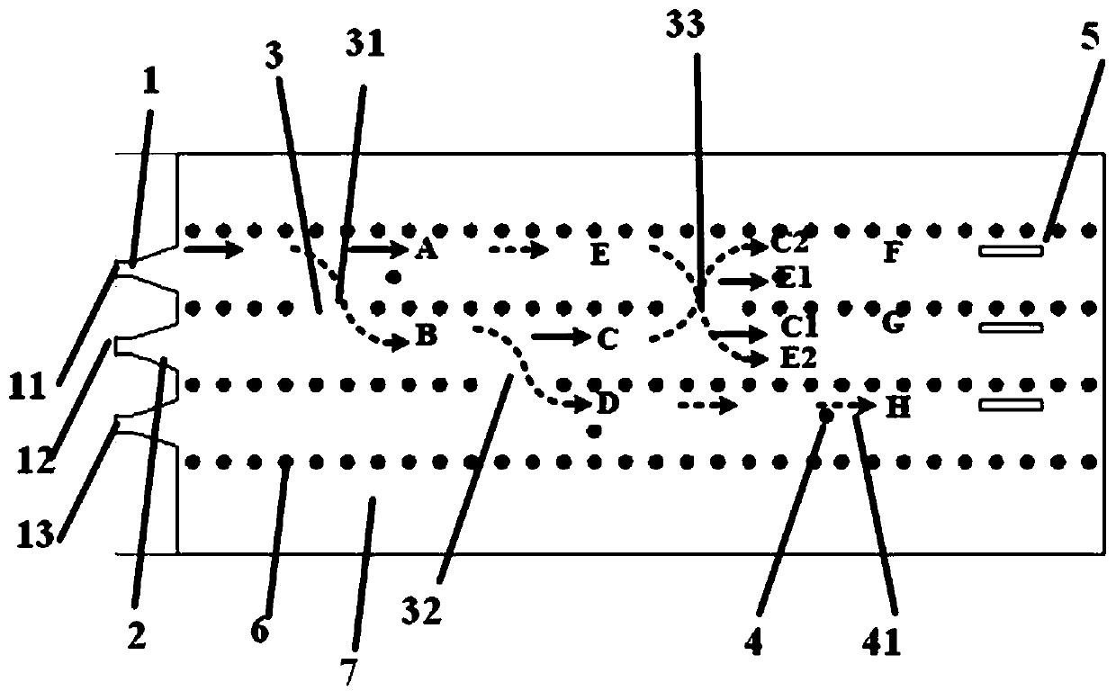
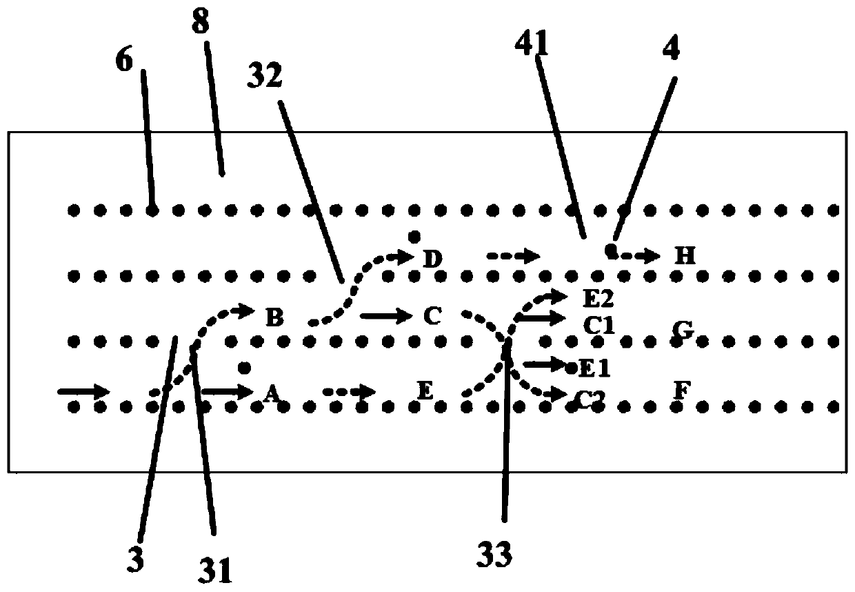
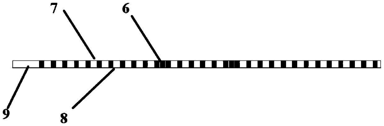
[0021] Such as Figure 1~3 As shown, the SIW-based multi-beam antenna system shown in this embodiment includes an input port 1 , a switching branch 2 , a network matrix and an antenna array 5 . The input port 1 , the conversion stub 2 and the antenna array 5 are all arranged on the dielectric substrate 9 . The various components are connected to each other through the conductive layer of the dielectric substrate 9 . The dielectric substrate 9 adopts various insulating media, and may also be an air medium. If an air medium is used, it is equivalent to no dielectric substrate. The thickness of the dielectric substrate 9 can be adjusted as required, generally between 0.1 mm and 5 mm. The network matrix includes SIW coupled phase modulator 3 ...


PUM


Abstract

The present invention discloses an SIW-based three-beam antenna system, which comprises conversion branches, a network matrix and an antenna array. The conversion branches are mainly used for mode transition of an electromagnetic signal from a microstrip transmission line to an SIW area; three SIW coupling phase modulators and one phase shifting unit are used for combination into a three-in-three-out network; and each column of the antenna array is connected to one port of the network matrix and the number of units of each column is greater than or equal to one. An SIW structure realizes a lowconsumption characteristic of signal transmission. By connecting to the antenna array, a radiation beam along an axial line and two axisymmetric beams can be realized. This design has the characteristics of small loss, simple structure, wide application range and the like.

Description

technical field [0001] The invention relates to the technical field of antennas, in particular to an SIW-based multi-beam antenna system. Background technique [0002] With the rapid development of wireless communication technology, the requirement for capacity is getting higher and higher. To address this trend, smart antennas play an important role in wireless communication systems. Smart antenna technology can improve the communication capacity of the system and achieve a higher signal-to-noise ratio. Smart antennas can be implemented using adaptive antenna technology and beamforming antenna technology. The maximum radiation direction of the adaptive antenna is aligned with the required site, and the null point is used to face the interfering station pattern. However, complex algorithms and a large amount of data need to be processed, and the response speed of the system is slow. The beamforming antenna has the advantages of simple structure, easy implementation, and ...

Claims


Application Information

Patent Timeline
Patent Type & Authority Applications(China)
IPC IPC(8): H01Q1/50H01Q13/10H01Q21/00H01Q25/00
Inventor 代喜望罗国清孙文范奎奎金华燕王明扬
Owner HANGZHOU DIANZI UNIV
Why Eureka
Try Eureka