Antenna sharing device

a technology of sharing device and antenna, applied in the direction of piezoelectric/electrostrictive/magnetostrictive devices, electrical apparatus, impedence networks, etc., can solve the problems of narrow transmission bandwidth, increased loss in a wide passband, and difficulty in maintaining a small loss in a wide transmission passband. achieve the effect of smooth crossband and low loss characteristi

Active Publication Date: 2016-08-16
SKYWORKS PANASONIC FILTER SOLUTIONS JAPAN
View PDF35 Cites 4 Cited by
  • Summary
  • Abstract
  • Description
  • Claims
  • Application Information

AI Technical Summary

Benefits of technology

[0013]The present invention has been achieved in consideration of the problems and an object of the invention is to realize both steepness in the crossband and a low loss characteristic in a passband in an antenna duplexer.

Problems solved by technology

However, Japanese Translation of PCT Application No. 2001-500697 relates to the technique for narrowing the bandwidth and does not disclose means realizing an antenna duplexer whose bandwidth is wide like 60 MHz in Band2.
That is, the transmission filter in the antenna duplexer disclosed in Japanese Translation of PCT Application No. 2001-500697 has a problem such that when steepness is increased to sufficiently assure attenuation in the reception band, the transmission bandwidth is narrowed, and a loss in a wide passband increases.
Particularly, the fractional bandwidth of the transmission / reception passband in Band2 is 3.2% and wide, and it is very difficult to maintain a small loss in the wide transmission passband.
Conventionally known techniques, however, have a problem such that when a low loss characteristic is realized in a wide band, sufficient steepness cannot be obtained.

Method used


Image

  • Antenna sharing device
  • Antenna sharing device
  • Antenna sharing device

Examples


first exemplary embodiment

[0066]A first exemplary embodiment of the present invention will now be described with reference to the drawings.

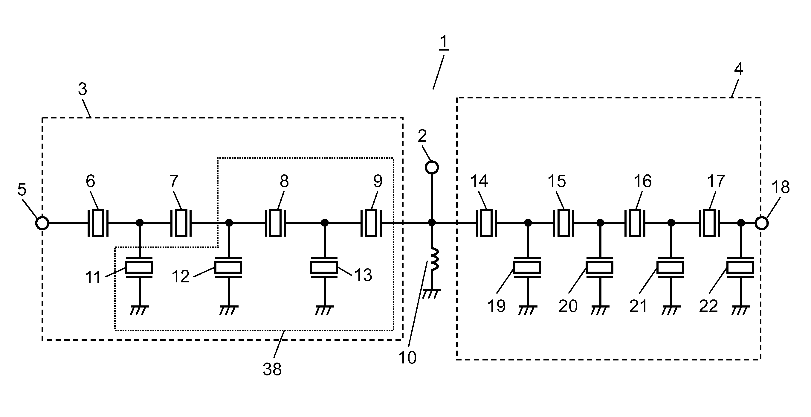
[0067]FIG. 1 is a schematic circuit diagram of antenna duplexer 1 in the first exemplary embodiment of the present invention.

[0068]Antenna duplexer 1 in the embodiment has first filter 3 as a transmission filter and second filter 4 as a reception filter each connected to antenna terminal 2. Antenna duplexer 1 has phase shifter 10 connected between first and second filters 3 and 4 to assure isolation between first and second filters 3 and 4.

[0069]Antenna duplexer 1 is, for example, for band 2. First filter 3 passes a signal in a first frequency band (transmission band) of 1850 MHz to 1910 MHz, and second filter 4 passes a signal in a second frequency band (reception band) of 1930 MHz to 1990 MHz higher than the first frequency band.

[0070]The circuit configuration of each of first and second filters 3 and 4 will now be described specifically.

[0071]First filter 3 has input t...

second exemplary embodiment

[0130]A second exemplary embodiment of the present invention will now be described.

[0131]FIG. 20 is a schematic circuit diagram of antenna duplexer 51 in the second exemplary embodiment of the invention.

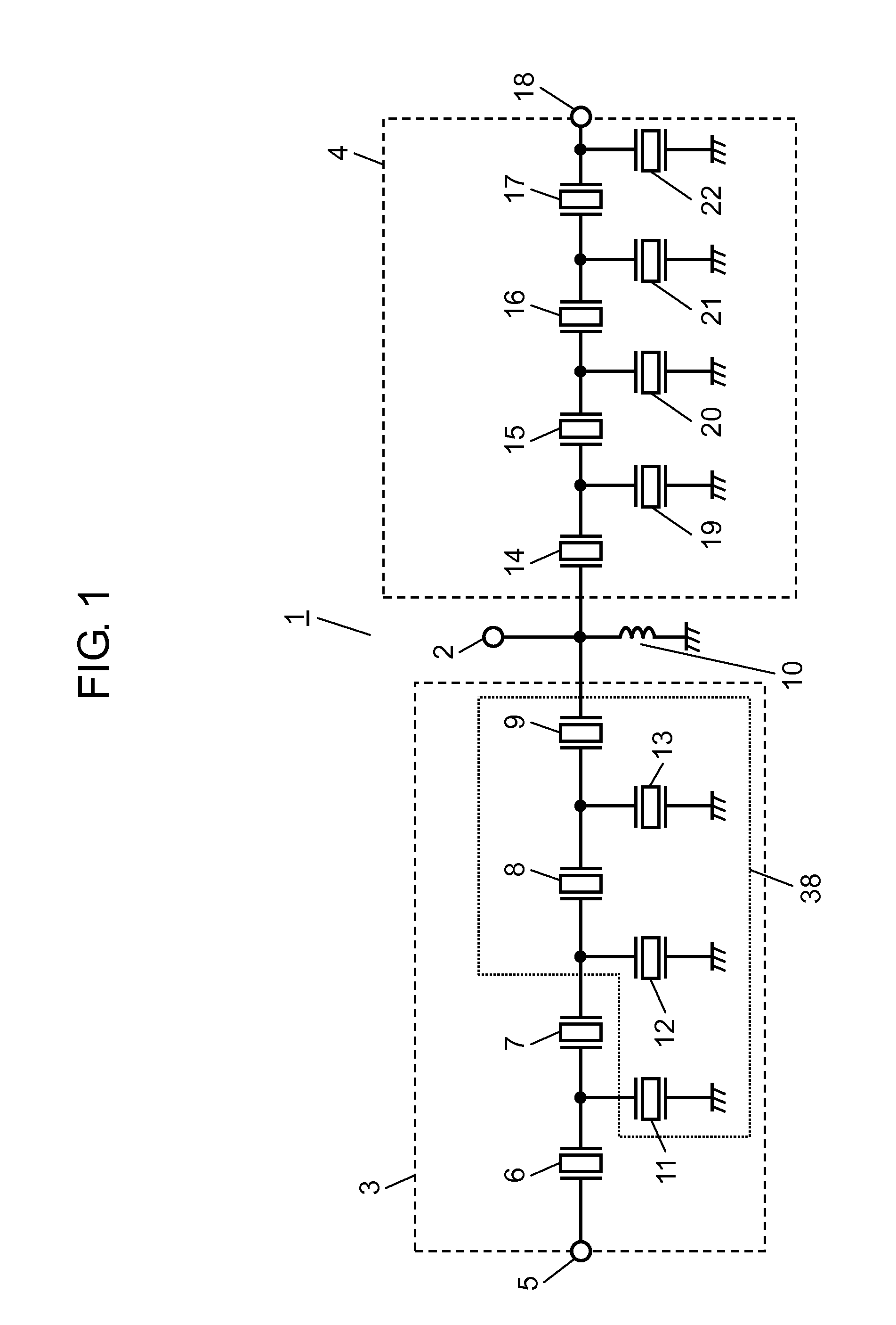
[0132]FIG. 21 is a schematic cross section of first filter 53 in antenna duplexer 51 in the second exemplary embodiment of the invention. Antenna duplexer 51 in the embodiment has, like antenna duplexer 1 shown in FIG. 1, first filter 53 and second filter 4. Unless otherwise specially described, the configuration of first filter 53 is similar to that of first filter 3 of the first embodiment.

[0133]First filter 53 in the embodiment has piezoelectric body 23 made of a lithium niobate based body having the Euler angles (φ, θ, ψ), electrode 25 provided on piezoelectric body 23 and exciting the main elastic wave having wavelength λ, and protective film 24 formed on piezoelectric body 23 so as to cover electrode 25 and having thickness larger than 0.2λ.

[0134]Protective film 24 has projecti...

third exemplary embodiment

[0156]Next, a third exemplary embodiment of the present invention will be described.

[0157]FIG. 24 is a schematic circuit diagram of antenna duplexer 61 in the third embodiment of the present invention.

[0158]In the embodiment, the configuration of first filters 3 and 53 described in the first and second exemplary embodiments is applied to second filter 54 of antenna duplexer 61.

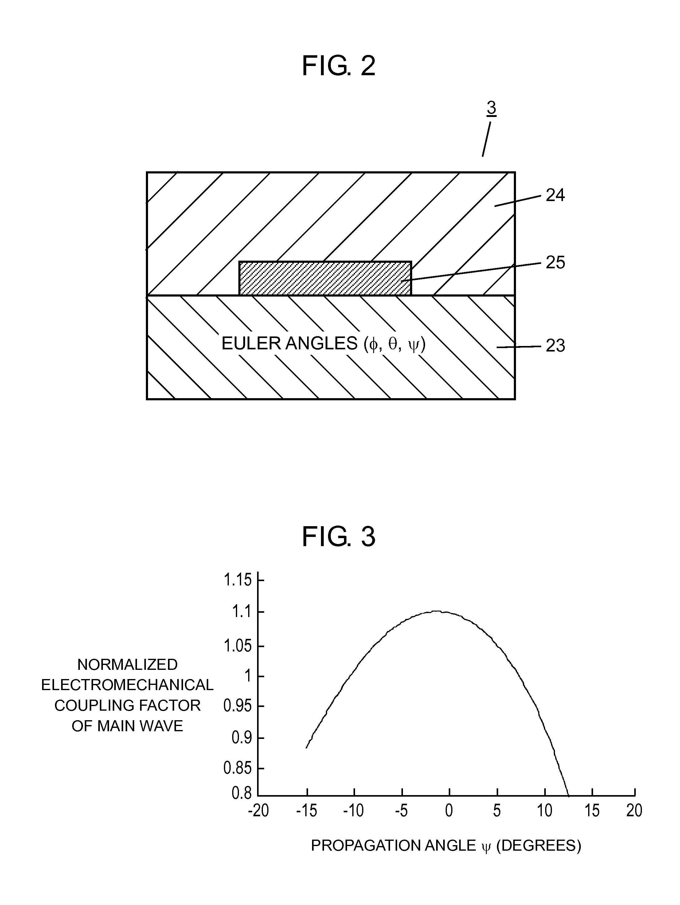
[0159]Concretely, the resonance frequency of fourth parallel resonator 19 in second filter 54 is set to be higher than that of the other parallel resonators, concretely, fifth, sixth, and seventh parallel resonators 20, 21, and 22. The electromechanical coupling coefficient of fourth parallel resonator 19 is set to be smaller than that of fifth, sixth, and seventh parallel resonators 20, 21, and 22. Consequently, the propagation angle ψ of the main elastic wave of fourth parallel resonator 19 is made different from that of the main elastic wave of fifth, sixth, and seventh parallel resonators 20, 21, and 22.

[0...


PUM


Abstract

An antenna duplexer has a first filter passing a signal in a first frequency band and a second filter passing a signal in a second frequency band which is higher than the first frequency band. The first filter includes a first series resonator having a lowest antiresonance frequency and second series resonators. A propagation angle of a main elastic wave of the first series resonator a propagation angle of a main elastic wave of each of the second series resonators are different from each other so that an electromechanical coupling coefficient of the first series resonator is smaller than an electromechanical coupling coefficient of the second series resonators.

Description

[0001]This application is a U.S. national stage application of the PCT international application No. PCT / JP2011 / 000869, filed Feb. 17, 2011.BACKGROUND OF THE INVENTION[0002]1. Technical Field[0003]The present invention relates to an antenna duplexer having a plurality of filters.[0004]2. Background Art[0005]In recent years, a cellular phone of a communication system of performing transmission / reception simultaneous communication such as W-CDMA (Wideband Code Division Multiple Access) is being rapidly spread. Accordingly, demand of an antenna duplexer such as a duplexer is increasing. As elements constructing an antenna duplexer, an SAW (Surface Acoustic Wave) element, a boundary elastic wave element, a BAW (Bulk Acoustic wave) element, and the like which are excellent from the viewpoints of small size, low height, and mass production are mainstream.[0006]Generally, an antenna duplexer has two filters (a transmission filter and a reception filter) to separate a signal in a transmissi...

Claims


Application Information

Patent Timeline
Patent Type & Authority Patents(United States)
IPC IPC(8): H03H9/64H03H9/72H03H9/02H03H9/56H03H9/70
CPCH03H9/02559H03H9/02984H03H9/568H03H9/6483H03H9/706H03H9/725
Inventor TSURUNARI, TETSUYAFUJIWARA, JOJINAKAMURA, HIROYUKI
Owner SKYWORKS PANASONIC FILTER SOLUTIONS JAPAN
Why Eureka
Try Eureka