System and method with interference suppression
A technology for interference suppression and interference suppression, which is applied in the field of interference suppression systems for interference signals, and can solve problems such as different estimation vectors
- Summary
- Abstract
- Description
- Claims
- Application Information
AI Technical Summary
Problems solved by technology
Method used
Image
Examples
no. 1 example
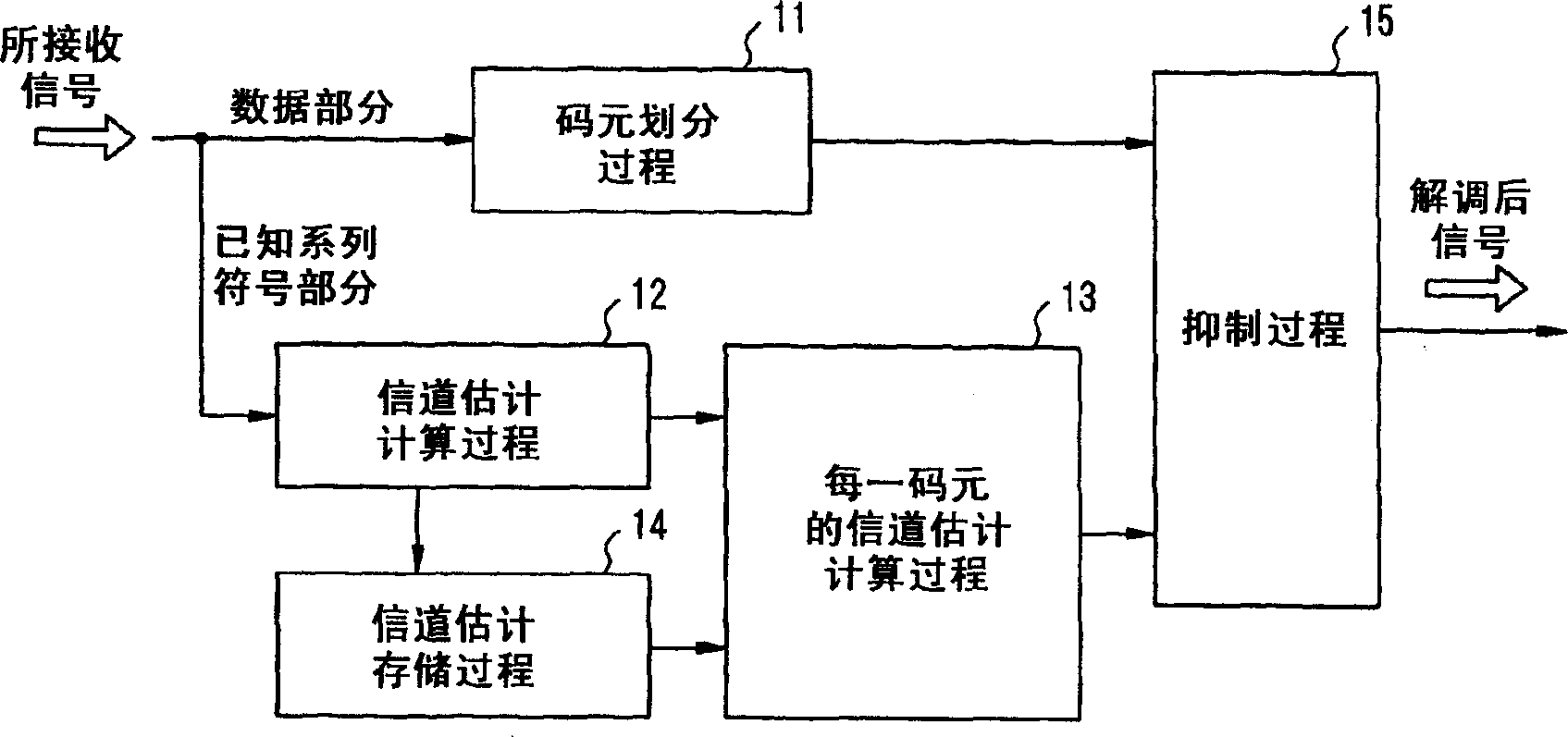
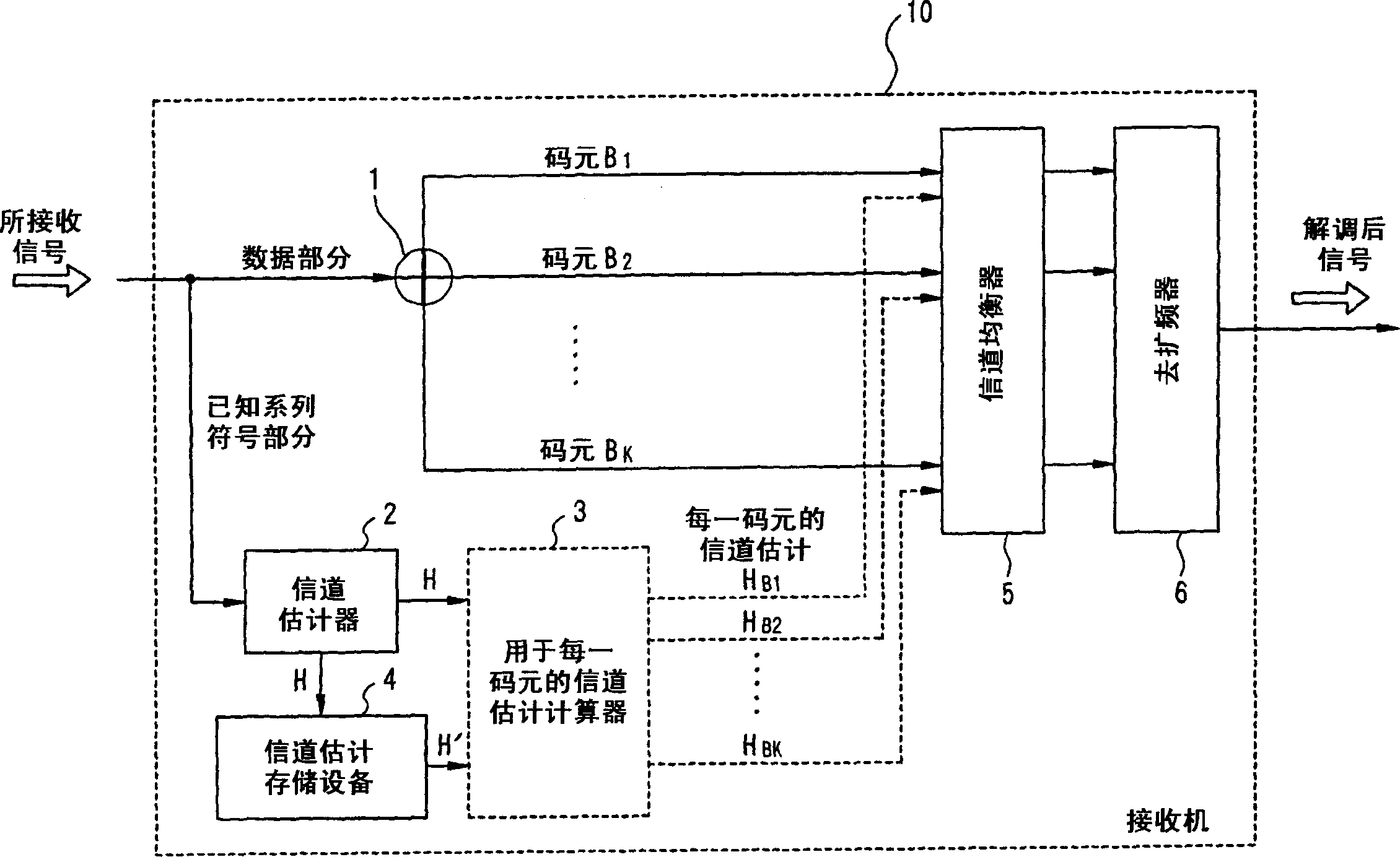
[0057] The following will refer to figure 2 A first embodiment of the present invention will be described in detail. exist figure 2 , the receiver 10 receives as a received signal a series of N time slots, namely slots S, in burst mode and in order of arrival 1 , time slot S 2 ,...,slot S N .
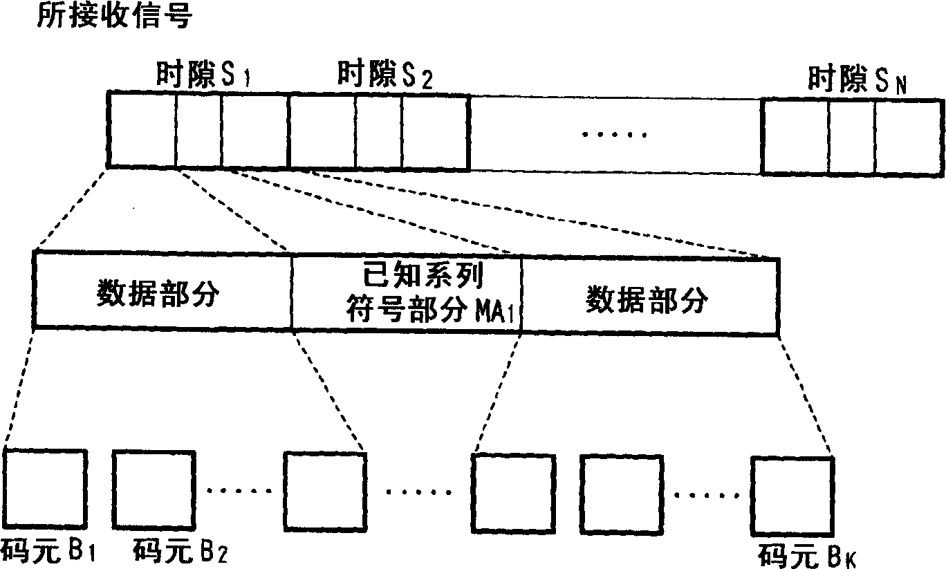
[0058] Such as image 3 As shown, the time slot S 1 , time slot S 2 , ...slot S N have data part respectively, namely data D 1 , data D 2 ,...,data D N , and the known series of symbols used to estimate the propagation channel for each path, namely MA 1 , MA 2 ,…,MA N . figure 2 The receiver 10 within , demodulates the slot S according to the order of arrival, and by demodulating 1 , time slot S 2 , ...slot S N .
[0059] First, the receiver 10 receives and demodulates a series of incoming time slots one by one. The symbol division device 1 of the receiver 10 receives the time slot S N When the nth time slot S in the N time slots N Divided into data parts (data D...
no. 2 example
[0065] A second embodiment of the present invention will be described below. FIG. 4 is a schematic diagram of a system applicable to an IMT (International Mobile Telecommunications)-2000 / CDMA / TDD system. In Figure 4, each time slot S 1 , S 2 , S 3 Both have a total of 2560 chips, including the midamble of the known series symbol part (256 chips) located in the center of the slot, and two data parts sandwiching the midamble of the known series symbol part, namely the data (1) (1104 chips) and data (2) (1104 chips), and a guard period (96 chips) at the right end of the slot.
[0066] Currently, in the CDMA / TDD system, downlink transmission of TTI=3 slots, in which the receiver 10 performs interference suppression reception by using single user detection (hereinafter referred to as SUD) regarded as a reception method. SUD refers to suppressing interference caused by delayed waves by performing channel equalization at a chip level to restore orthogonality of lost user signals,...
no. 3 example
[0076] In the above-mentioned second embodiment, the channel estimation calculator 3 for each symbol in the demodulation slot S 2 can be used to execute Figure 7 The operation exchange shown. The operation exchange will be described below.
[0077] First, obtain the channel estimation vector H of the current time slot (step S701). Next, obtain the channel estimation vector H' of the previous time slot (step S702). Then, a difference vector G between the channel estimation vector H and the channel estimation vector H' is calculated (step S703). For example, to calculate the slot S 2 The channel estimation vector H 2 with slot S 1 The channel estimation vector H 1 The difference vector G between.
[0078] When the magnitude |G| of the calculated difference vector G is greater than the predetermined threshold "g", the channel estimation vector of each symbol is calculated by performing an interpolation on the channel estimation vector H and the channel estimation vector ...
PUM
 Abstract
Description
Claims
Application Information
 - R&D
- Intellectual Property
- Life Sciences
- Materials
- Tech Scout
- Unparalleled Data Quality
- Higher Quality Content
- 60% Fewer Hallucinations
Browse by: Latest US Patents, China's latest patents, Technical Efficacy Thesaurus, Application Domain, Technology Topic, Popular Technical Reports.
© 2025 PatSnap. All rights reserved.Legal|Privacy policy|Modern Slavery Act Transparency Statement|Sitemap|About US| Contact US: help@patsnap.com


