System and method of interference suppression

a suppression system and interference technology, applied in the field of system and method of interference suppression, can solve the problem that the actual channel estimate vector of a data part becomes different from the channel estimate vector

Inactive Publication Date: 2007-12-11
NTT DOCOMO INC
View PDF15 Cites 8 Cited by
  • Summary
  • Abstract
  • Description
  • Claims
  • Application Information

AI Technical Summary

Benefits of technology

[0027]That is to say, the present invention can perform more precise interference suppression for a received signal than conventional arts by dividing a data part of a received slot into several blocks, calculating a channel estimate vector for each block on the basis of a channel estimate vector of previous slot and a channel estimate vector for the slot, and performing a calculation including a channel equalizing calculation for each block.

Problems solved by technology

However, under a high speed fading, this conventional system has a problem that an actual channel estimate vector for a data part becomes different from a channel estimate vector for a known series symbol because of fading.

Method used


Image

  • System and method of interference suppression
  • System and method of interference suppression
  • System and method of interference suppression

Examples


first example

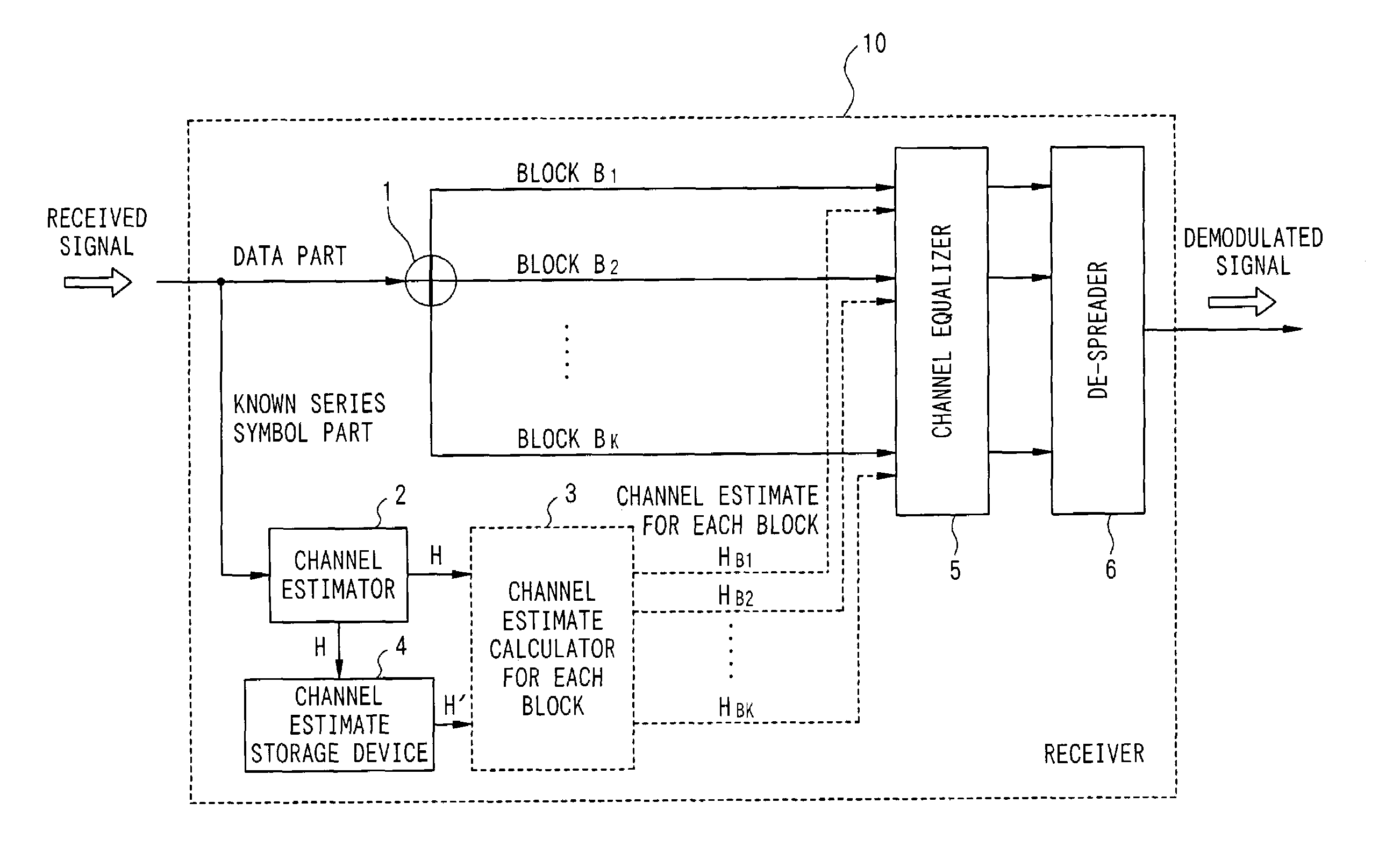
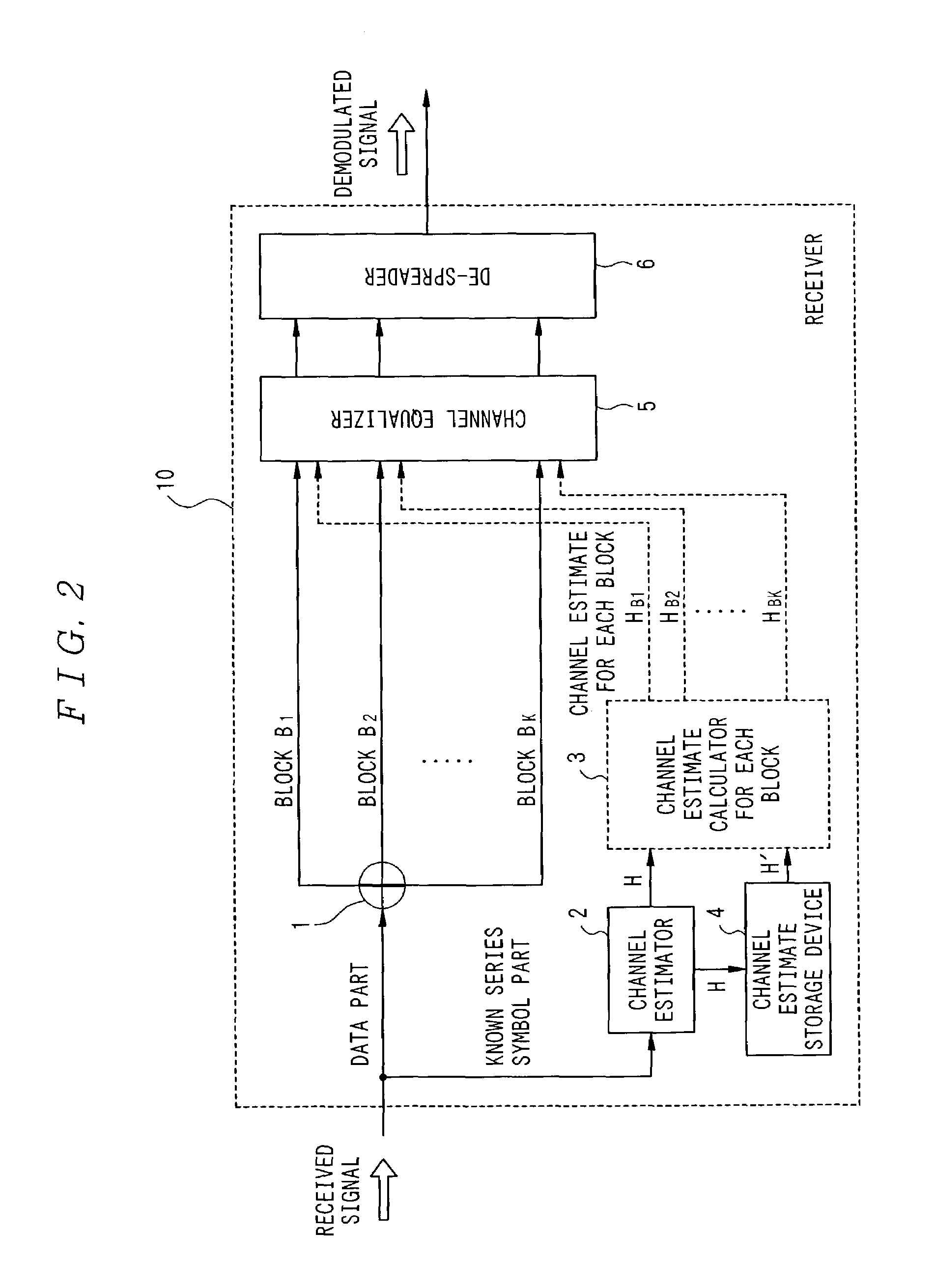
[0057]Next, a first example of the present invention will be described in detail with reference to FIG. 2. In FIG. 2, receiver 10 receives a series of N slots, i.e., slot S1, slot S2, . . . , slot SN in the order of arrival as a received signal in burst mode.

[0058]As it is shown in FIG. 3, slot S1, slot S2, . . . , slot SN have a data part, i.e., data D1, data D2, . . . , data DN, and a known series symbol for estimating a propagation channel for each path, i.e., MA1, MA2, . . . , MAN, respectively. Receiver 10 in FIG. 2 demodulates slot S1, slot S2, . . . , slot SN in the order of arrival via demodulation described below.

[0059]First, receiver 10 receives and demodulates a series of incoming slots one by one. Block dividing section 1 of receiver 10 divides nth slot SN in N slots into a data part (data DN) and a known series symbol part (MAN) on receiving the slot SN. Data DN is further divided into K blocks as shown in FIG. 3, i.e., block B1, block B2, . . . , block BK. Each of thes...

second example

[0064]Now, a second example of the present invention will be described. FIG. 4 is a schematic view of the system adapted for IMT (International Mobile Telecommunications)—2000 / CDMA / TDD system. In FIG. 4, each of the slots S1, S2, S3 has 2560 chips in all, consisting of a known series symbol part Midamble (256 chips) placed at the center of a slot, two data parts sandwiching the known series symbol part Midamble, i.e., Data (1) (1104 chips) and Data (2) (1104 chips), and Guard Period (96 chips) at the right end of a slot.

[0065]Now, a downlink transmission of TTI=3 Time slot in CDMA / TDD system, where receiver 10 performs interference suppression receiving by using Single User Detection (referred to SUD hereinafter) as a receiving method is considered. SUD refers to suppressing interference caused by a delayed wave by performing a channel equalization at the chip level to restore the lost orthogonality of the user signals and then performing de-spreading. SUD is described in “Data Dete...

third example

[0074]In the above-mentioned second example, channel estimate calculator for each block 3 in demodulating slot S2 can be adapted to perform operation switching as shown in FIG. 7. Now, the operation switching will be described.

[0075]First, a channel estimate vector H for the current slot is obtained (step S701). Next, a channel estimate vector H′ for a previous slot is obtained (step S702). Then, a difference vector G between a channel estimate vector H and a channel estimate vector H′ (step S703) is calculated. For example, a difference vector G between a channel estimate vector H2 for slot S2 and a channel estimate vector H1 for slot S1 is calculated.

[0076]When magnitude of the calculated difference vector G, |G| is greater than a predetermined threshold “g”, a channel estimate vector for each block is calculated by performing primary interpolation on a channel estimate vector H and a channel estimate vector H′ (steps S704->S705). For example, channel estimate vectors HB1, HB2, . ...


PUM


Abstract

To perform interference suppression for a received signal more precisely. Block dividing section divides a data part of a received slot into several blocks. Channel estimator calculates a channel estimate vector for each block and stores it into channel estimate storage device. Channel estimate calculator for each block calculates a channel estimate vector for each block by using a channel estimate vector calculated with a known series symbol part for the (current) slot and a channel estimate vector for a known series symbol part for a previous slot stored in channel estimate storage device. Then, channel equalizer and de-spreader perform a calculation such as a channel equalizing calculation by using a channel estimate vector for each block at each block.

Description

BACKGROUND OF THE INVENTION[0001]1. Field of the Invention[0002]The present invention relates to system and method of interference suppression, more specifically to system and method of interference suppression for suppressing interference signal in mobile communication.[0003]2. Description of the Related Art[0004]In mobile communication systems such as CDMA (code division multiple access) and TDD (time division duplex), an interference suppression receiving method for suppressing interference caused by a delayed wave or a multi-user is implemented for increasing capacity for subscribers. A receiver calculates a channel estimate vector by using a known series symbol within a received slot for estimating variations in phase and amplitude of a received signal resulting from arrival timing for each chip level in each received slot or fading fluctuation of each propagation channel, and performs a channel equalizing calculation by using the channel estimate vector to suppress interferenc...

Claims


Application Information

Patent Timeline
Patent Type & Authority Patents(United States)
IPC IPC(8): H04B1/00H04B1/7105H04B1/707H04B1/7115H04L25/02
CPCH04L25/0232
Inventor ISHII, HIROYUKIISHIGURO, TAKAYUKII
Owner NTT DOCOMO INC
Why Eureka
Try Eureka