
Electronic sphygmomanometer

An electronic sphygmomanometer and blood pressure technology, applied in vascular assessment, cardiac catheterization, etc., can solve the problems of increased noise, inability to correctly calculate the characteristics of arterial wave waveform, and deterioration

Inactive Publication Date: 2003-09-10
OMRON HEALTHCARE CO LTD
View PDF2 Cites 13 Cited by
  • Summary
  • Abstract
  • Description
  • Claims
  • Application Information

AI Technical Summary

Problems solved by technology

In other words, if measurement accuracy is required, in order to obtain correction information, an electronic sphygmomanometer with an existing method for calibration (for example, an electronic sphygmomanometer with the vibration method) should be purchased separately, and the electronic sphygmomanometer with the SPD method and the existing method should be purchased separately. Both electronic sphygmomanometers work, and the value of the existing electronic sphygmomanometer, that is, the calibration information must be input into the electronic sphygmomanometer of the SPD method, and its operation becomes very complicated
[0014] Although the SPD method theoretically pressurizes the arm cuff 2 to any pressure, the blood pressure can be calculated by capturing the arterial wave at least 1 beat under this pressure, but when the pressurization value is far greater than the blood pressure, the body can transmit The arterial wave will be very weak, and the noise will be relatively louder, that is, the S / N ratio will become worse, and the waveform feature quantity of the arterial wave cannot be calculated correctly, thus bringing a large error to the measurement

Method used


Image

  • Electronic sphygmomanometer
  • Electronic sphygmomanometer
  • Electronic sphygmomanometer

Examples


Embodiment 1

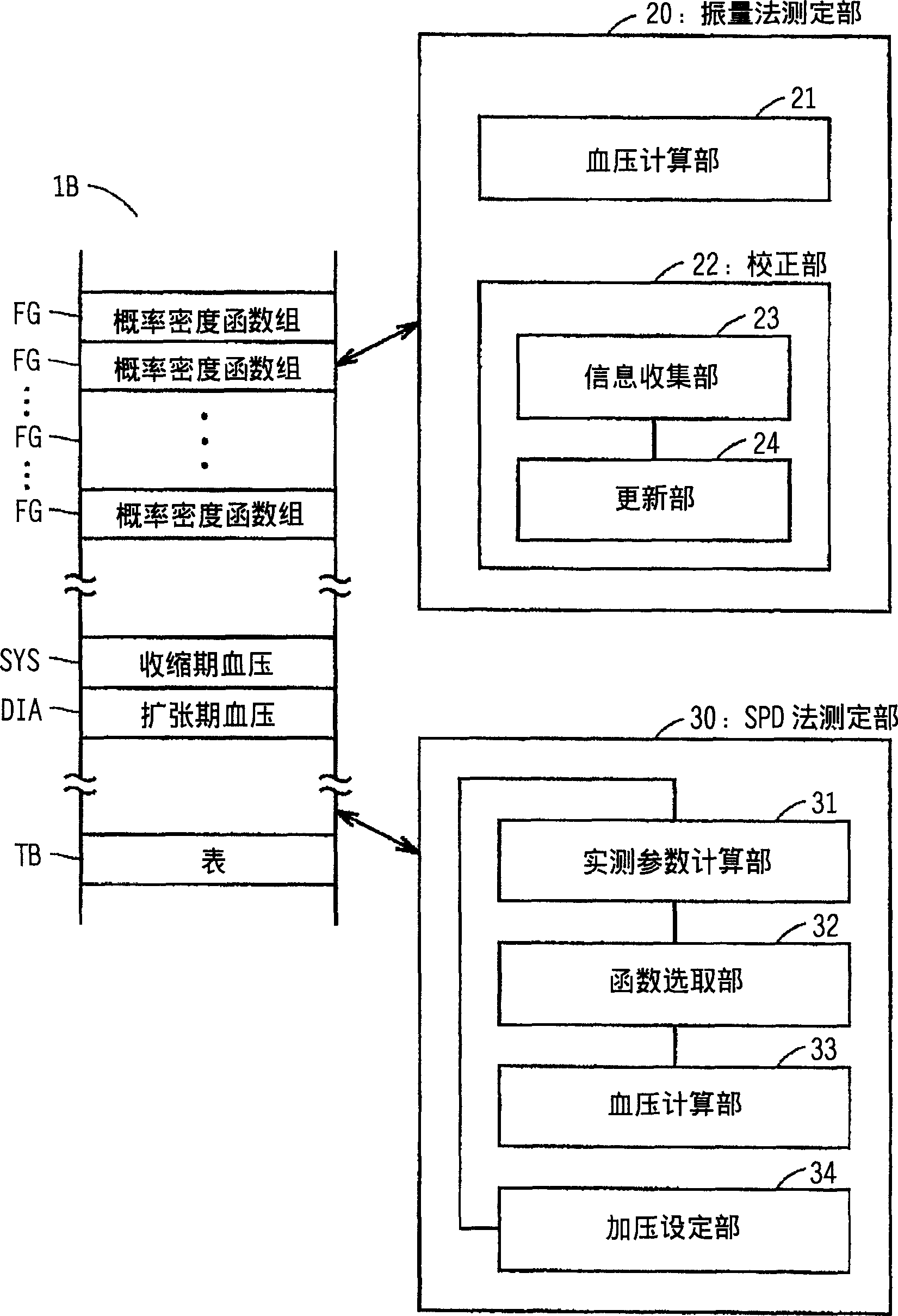
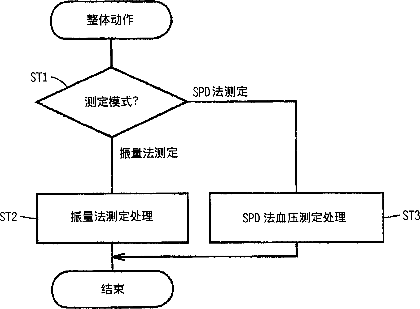
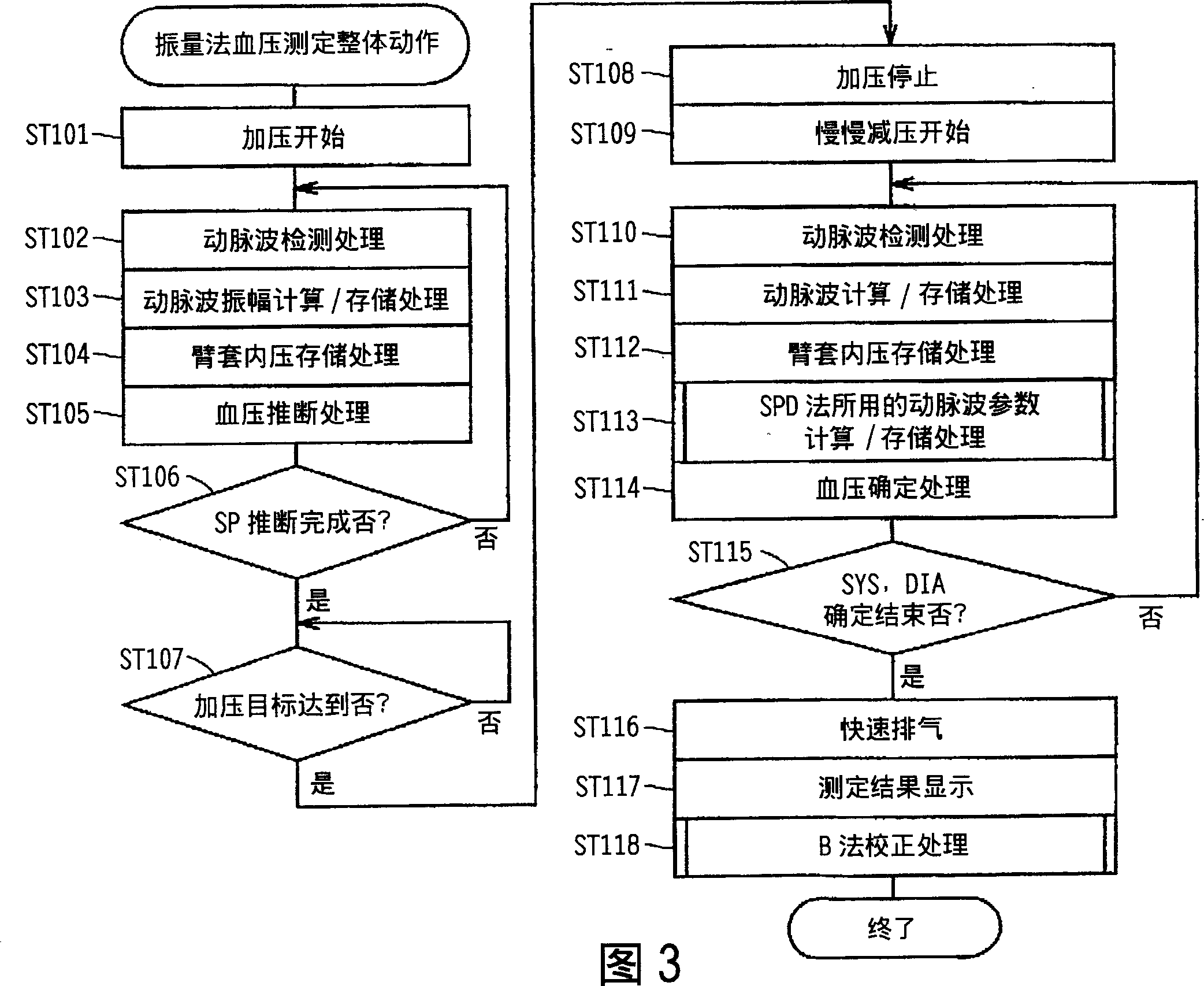
[0075] In the first embodiment, processing for improving the measurement accuracy of the SPD method is performed based on the information detected by the vibration measurement method. According to the equipment structure and overall action of the electronic sphygmomanometer, the blood pressure measurement operation completed by the vibration method, the blood pressure measurement principle implemented by the SPD method, the SPD method blood pressure measurement operation of this embodiment, and the SPD applicable to this embodiment The individual correction principles of the law are described in sequence for this process.

[0076] (equipment configuration)

[0077] The electronic sphygmomanometer involved in each embodiment has the same Figure 14 The shown configurations have the same device configuration, and therefore, description thereof will be omitted. figure 1 It is a functional configuration diagram of electronic blood pressure measurement according to each embodimen...

Embodiment 2

[0136] According to the principle of SPD, although the blood pressure can be calculated at any level of the internal pressure of the cuff, when there is a large gap between the internal pressure of the cuff and the actual blood pressure, the amplitude of the arterial wave becomes smaller, and the S / N ratio decreases. The probability density function will not provide the correct extrapolated value of blood pressure, which will lead to the loss of precision of blood pressure calculation. Therefore, for the second embodiment, the function of automatically setting the pressure by the pressurization setting part 34 is applied to the blood pressure measurement function of the SPD according to the first embodiment, so as to optimize the pressurization value of the SPD method. As a result, it is possible to measure Higher precision.

[0137] (Optimization of pressure setting for SPD method)

[0138] The flow process of the overall action of the blood pressure measurement carried out ...


PUM


Abstract

Gauge comprises an oscillating measurement section (20) suitable for making highly accurate blood pressure measurements using suitable biogenic information. Quick measurements can be made using a single pulse determination section (30).

Description

technical field [0001] The present invention relates to an electronic sphygmomanometer, in particular to an electronic sphygmomanometer using a squeeze part (hereinafter referred to as an arm cuff) for injecting fluid such as air to squeeze limbs or other parts of the body . Background technique [0002] The method of measuring blood pressure using an arm cuff is that the artery is compressed by the arm cuff, and the internal volume of the artery changes after being compressed by the arm cuff, which is captured during the process of slowly changing the pressure inside the arm cuff (hereinafter referred to as the cuff internal pressure). A method of calculating and determining blood pressure based on various arterial signals (hereinafter referred to as arterial waves) generated by changes in internal volume. This method of measuring blood pressure is called the vibration method. [0003] Figure 14 It is a schematic diagram of the equipment configuration of the electronic s...

Claims


Application Information

Patent Timeline
IPC IPC(8): A61B5/022A61B5/021
CPCA61B5/02225A61B5/021A61B5/02116
Inventor 白崎修
Owner OMRON HEALTHCARE CO LTD
Learn More