
Method for dynamically switching blood pressure measurement model

Pending Publication Date: 2021-09-16
INVENTEC PUDONG TECH CORPOARTION +1
View PDF6 Cites 0 Cited by
  • Summary
  • Abstract
  • Description
  • Claims
  • Application Information

AI Technical Summary

Benefits of technology

The present patent provides a method for improving the accuracy of blood pressure measurements and minimizing the impact on the user's daily routine. This is achieved by providing alternative blood pressure models for different conditions, which can be automatically switched based on the user's needs. This results in a more flexible and accurate wearable blood pressure measurement device compared to traditional devices that offer only one type of measurement mode and have fixed measurement accuracy.

Problems solved by technology

Uncontrolled high blood pressure (BP) can lead to heart attack, stroke, heart failure, and other serious life threats.
The cuff-based method is intrusive because one of the arms of the user has to be cuffed for at least 30 seconds to obtain an accurate reading.
Therefore, cuff-based method is not suitable for a long-term blood pressure measurement, all day for instance.
However, since the result of the cuff-based blood pressure measurement is considered “gold standard”, the cuffless blood pressure measurement is naturally less accurate.
Therefore, the user needs to take an extra effort and time to provide sensing data in different situations.
On the other hand, considering the actual application scenario of the wearable blood pressure measurement device, the ECG signal-based blood pressure measurement may not be suitable in some situation, when users are sleeping for instance, for users do not always have spare hands to measure the blood pressure.
Overall, the wearable blood pressure measurement devices nowadays lack of flexibility in practical usage.

Method used


Image

  • Method for dynamically switching blood pressure measurement model
  • Method for dynamically switching blood pressure measurement model
  • Method for dynamically switching blood pressure measurement model

Examples


Embodiment Construction

[0013]In the following detailed description, for purposes of explanation, numerous specific details are set forth in order to provide a thorough understanding of the disclosed embodiments. It will be apparent, however, that one or more embodiments may be practiced without these specific details. In other instances, well-known structures and devices are schematically shown in order to simplify the drawings.

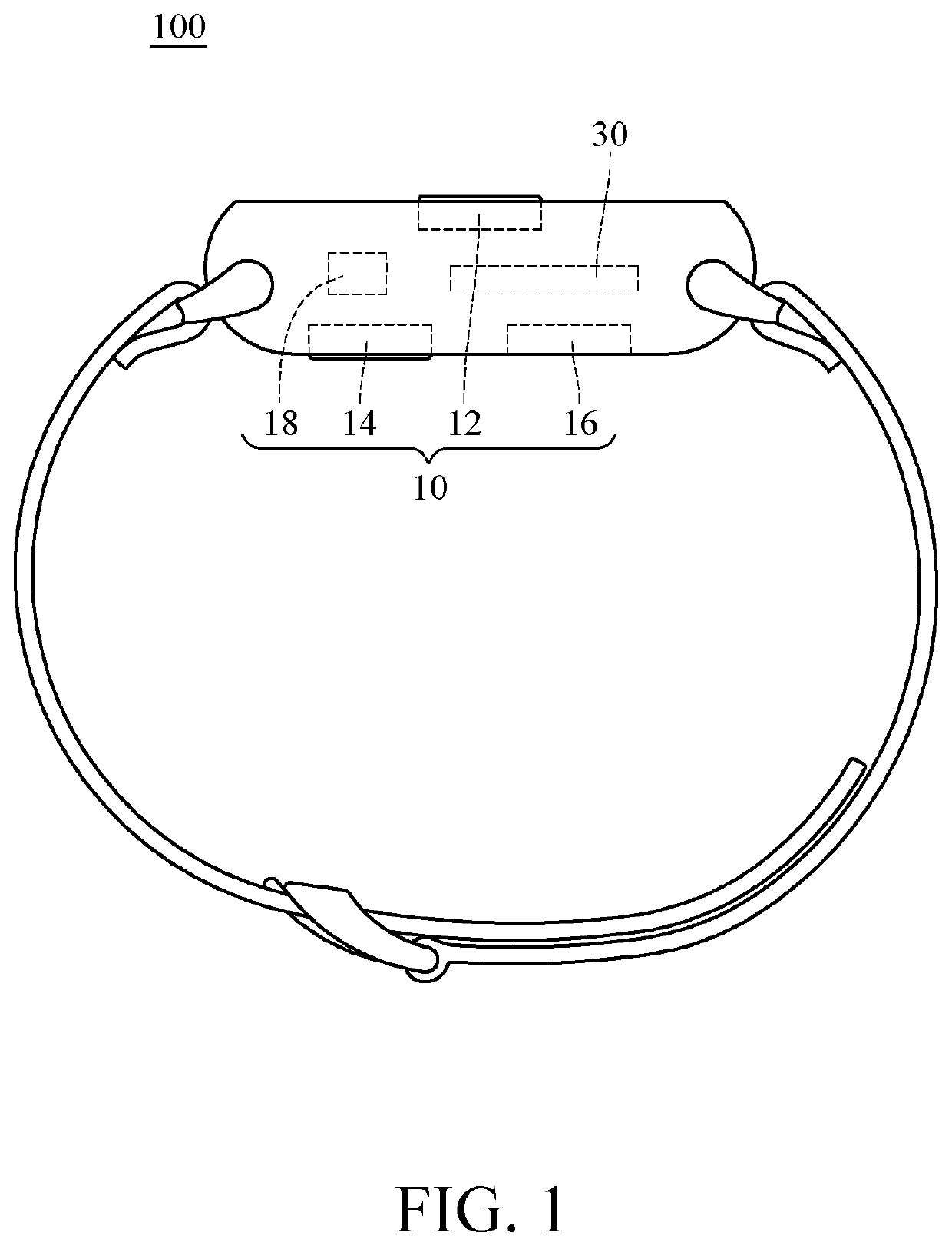
[0014]The method for dynamically switching blood pressure measurement models according to an embodiment of the present disclosure is adapted to a wearable blood pressure measurement device preferably. Please refer to FIG. 1, which is a schematic diagram of a wearable blood pressure measurement device 100. The type of the wearable blood pressure measurement device 100 recited in FIG. 1 is cuffless. However, the present disclosure does not limit the structure of the embodiment above.

[0015]As recited as FIG. 1, the wearable blood pressure measurement device 100 comprises a biosignal s...


PUM


Abstract

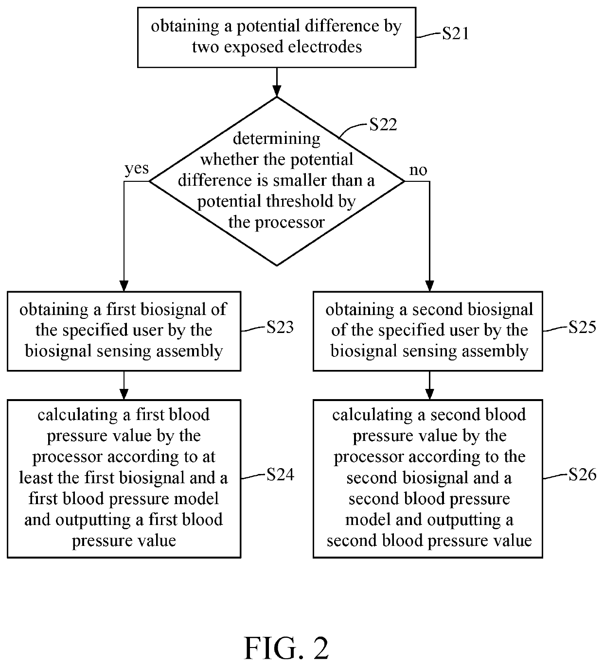
A method for dynamically switching blood pressure measurement model, adapted to a wearable blood pressure measurement device with a biosignal sensing assembly and a processor, wherein said biosignal sensing assembly comprises two exposed electrodes, comprises: obtaining potential difference by said two exposed electrodes; determining whether potential difference is smaller than potential threshold by processor; obtaining first biosignal of specified user by biosignal sensing assembly when potential difference is smaller than the potential threshold; calculating first blood pressure value by processor according to at least first biosignal and first blood pressure model and outputting first blood pressure value; obtaining second biosignal of specified user by biosignal sensing assembly when potential difference is not smaller than the potential threshold, wherein types of first and second biosignal are different; and calculating second blood pressure value by processor according to second biosignal and second blood pressure model and outputting second blood pressure value.

Description

CROSS-REFERENCE TO RELATED APPLICATIONS[0001]This non-provisional application claims priority under 35 U.S.C. § 119(a) on Patent Application No(s). 202010178885.X filed in China on Mar. 15, 2020, the entire contents of which are hereby incorporated by reference.BACKGROUND1. Technical Field[0002]This disclosure relates to a method for switching blood pressure measurement model, and more particularly to a method for dynamically switching blood pressure measurement model.2. Related Art[0003]Cardiovascular related diseases have been proven to be highly related to heart rate and blood pressure. Uncontrolled high blood pressure (BP) can lead to heart attack, stroke, heart failure, and other serious life threats. Therefore, accurate measurement of blood pressure is necessary to prevent unwanted events. According to the validation protocol followed by American National Standards Institute (ANSI), Association for the Advancement of Medical Instrumentation (AAMI) and International Organizatio...

Claims


Application Information

Patent Timeline
IPC IPC(8): A61B5/022A61B5/024A61B5/0402A61B5/00
CPCA61B5/02225A61B5/02416A61B5/0402A61B2562/0219A61B5/7264A61B2562/085A61B5/6802A61B5/021A61B5/022A61B5/1116A61B5/681A61B5/7267G06F16/9035G06N3/08G06N3/045A61B5/02108A61B5/02125A61B5/256A61B5/318A61B2560/0223A61B5/4809A61B5/1118
Inventor CHEN, TRISTA PEI-CHUNSOESENO, JONATHAN HANSCHEN, WEI-CHAO
Owner INVENTEC PUDONG TECH CORPOARTION
Learn More