
Blood pressure measurement device

a blood pressure measurement and blood pressure technology, applied in the field of blood pressure measurement devices, can solve the problems of inability to perform sufficient correction, inability to change the character unlimitedly, and blood pressure measurement errors, so as to reduce the blood pressure measurement error and the effect of blood pressure measurement error reduction

Active Publication Date: 2017-07-18
OMRON HEALTHCARE CO LTD
View PDF26 Cites 0 Cited by
  • Summary
  • Abstract
  • Description
  • Claims
  • Application Information

AI Technical Summary

Benefits of technology

The present invention provides a blood pressure measurement device that improves the accuracy of blood pressure measurement. The device includes an increasing unit for increasing the volume of the fluid bladder and a pressurizing unit for pressurizing the fluid bladder. The device can bring the detection accuracy of the volume change of the blood vessel close to a constant level regardless of the pressure of the fluid bladder, reducing blood pressure measurement error. This also eliminates the necessity of correcting the volume of the fluid bladder which is different according to the perimeter of the measurement portion.

Problems solved by technology

Therefore, an error occurs in blood pressure measurement.
However, this change character unlimitedly changes according to a wrapping method of the fluid bladder, a thickness of an arm, softness of a human body, and the like, and sufficient correction cannot be performed.
Further, it is necessary to perform multiple, more complicated corrections (flow amount detection, size detection of a measurement portion, wrapping condition detection, detection of softness of a human body, and the like), and a complicated apparatus is needed.
Therefore, this is not practical.
However, it is difficult to reduce the pressure in order to close the valve every time a pulse wave appears.

Method used


Image

  • Blood pressure measurement device
  • Blood pressure measurement device
  • Blood pressure measurement device

Examples


first embodiment

[0127]In the first embodiment, a blood pressure measurement device for measuring a blood pressure during depressurizing process of a fluid bladder will be described.

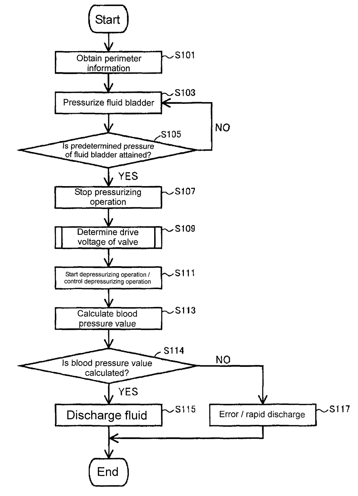
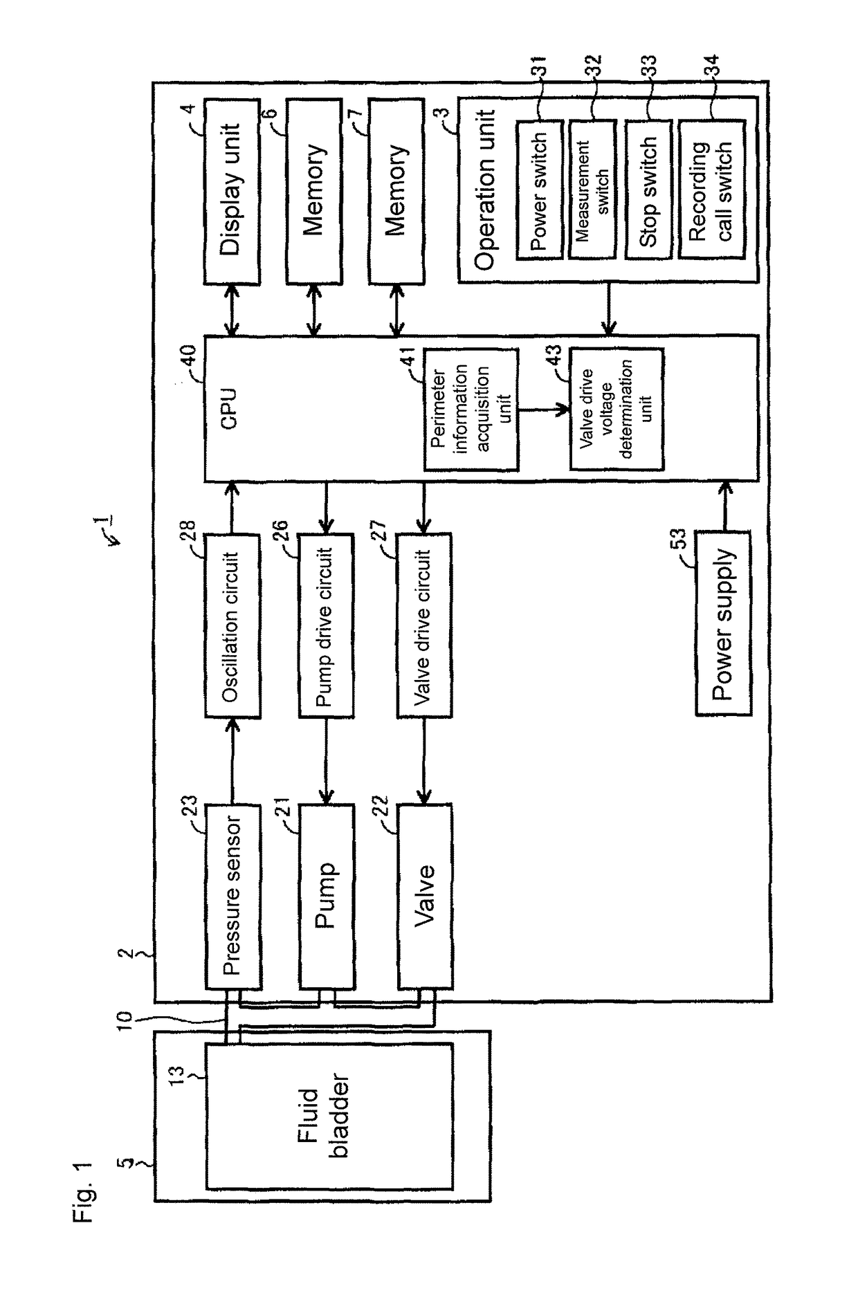
[0128]Referring to FIG. 1, a sphygmomanometer 1 serving as a blood pressure measurement device according to the first embodiment includes a main body 2, a cuff 5 wrapped around a measurement portion, and these are connected via a tube 10. An operation unit 3 such as a switch and a display unit 4 for displaying measurement results and the like are arranged on a front surface of the main body 2. The operation unit 3 includes a power switch 31 for giving instruction for turning on and off the power supply, a measurement switch 32 for giving an instruction for starting measurement, a stop switch 33 for giving an instruction for stopping measurement, and a recording call switch 34 for calling and displaying a recorded measurement value. A cuff 5 is arranged with a fluid bladder 13. A fluid injected into the fluid bladder 13 a...

modification 1

[Modification 1]

[0143]A modification of the processing executed in response to an operation of the measurement switch 32 in the sphygmomanometer 1 will be described with reference to a flowchart of FIG. 8. The processing shown in FIG. 8 is performed in the same manner as the second specific example shown in FIG. 3. That is, in steps S201 to S205, the perimeter of the measuring portion is estimated based on the pressurizing time in which the pressure of the fluid bladder 13 attains the predetermined pressure, and in the subsequent pressurizing process, the CPU 40 estimates the systolic blood pressure value based on an internal pressure change of the fluid bladder 13 obtained from the pressure sensor 23 in step S301. In step S303, the pressure of the fluid bladder 13 at the end of the pressurizing process is calculated. The sphygmomanometer 1 is configured to calculate a blood pressure value based on an internal pressure change of the fluid bladder 13 obtained in depressurizing proces...

second modification

[Second Modification]

[0151]A hardware configuration of a sphygmomanometer 1-1, i.e., a modification of the sphygmomanometer 1, will be described with reference to FIG. 13. Referring to FIG. 13, the sphygmomanometer 1-1 further includes a tank 54 storing a non-pressurized fluid and connected to the fluid bladder 13 via the tube 10, in addition to the hardware configuration of the sphygmomanometer 1 as shown in FIG. 1. The tank 54 is connected to the pump 51 and the valve 52. The pump 51 and the valve 52 are respectively connected to a pump drive circuit 56 and a valve drive circuit 57. Further, the pump drive circuit 56 and the valve drive circuit 57 are connected to the CPU 40. The CPU 40 executes a predetermined program stored in the memory 6 based on an operation signal inputted with the operation unit 3. The CPU 40 determines voltages for driving the pump 51 and the valve 52, and outputs control signals to the pump drive circuit 56 and the valve drive circuit 57 according to the ...


PUM


Abstract

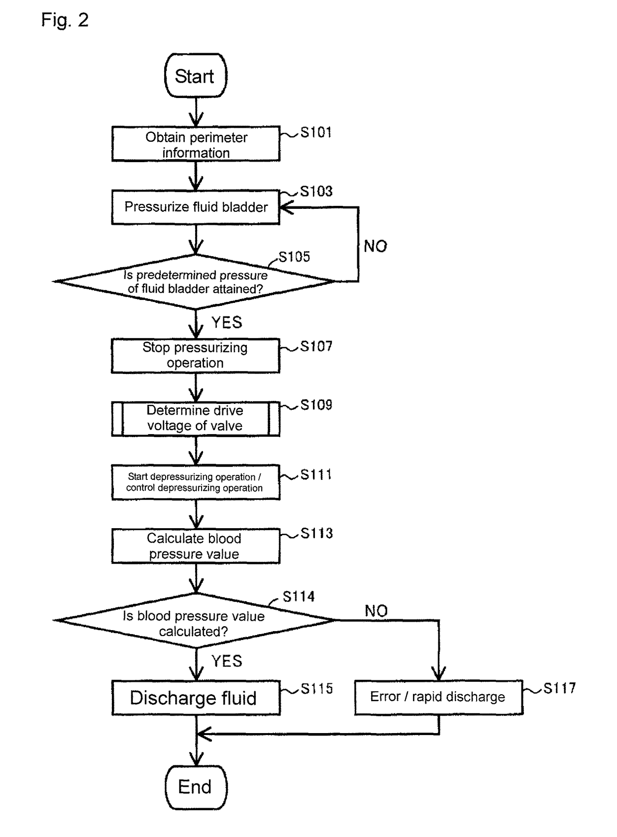
In a sphygmomanometer, a value representing a perimeter of a measuring portion is obtained. A parameter for controlling a drive voltage of a pump is determined based on the value. The drive voltage is determined based on the parameter and an internal pressure of a fluid bladder to pressurize the fluid bladder. In pressurizing process, a diastolic blood pressure value is calculated. A systolic blood pressure value is estimated, and when the internal pressure of the fluid bladder reaches the pressure, the pressurizing is stopped. A gap of a valve for discharging the fluid from the fluid bladder is determined based on a perimeter of a measuring portion, and the fluid bladder is depressurized with the gap constant. In the depressurizing process, the systolic blood pressure value is calculated. When the systolic blood pressure value is calculated, the fluid is discharged from the fluid bladder, and the measurement is terminated.

Description

TECHNICAL FIELD[0001]This invention relates to a blood pressure measurement device, and more particularly to a blood pressure measurement device for measuring blood pressure using a cuff including a fluid bladder.BACKGROUND ART[0002]An example of blood pressure calculation method used by an electronic sphygmomanometer is an oscillometric method. In the oscillometric method, a cuff including a fluid bladder wrapped around a portion of a living body is pressurized and depressurized. A volume change of the fluid bladder transmitted by a volume change of a pressurized blood vessel is recognized as a pressure change of the fluid bladder (pressurized pulse wave amplitude), and thereby a blood pressure is calculated.[0003]The fluid bladder has such property that the pressure of the fluid bladder and the volume of the fluid bladder have a relationship as shown in FIG. 33. More specifically, the description will be made with reference to FIG. 33. In a region in which the pressure of the flui...

Claims


Application Information

Patent Timeline
Patent Type & Authority Patents(United States)
IPC IPC(8): A61B5/02A61B5/0225A61B5/022
CPCA61B5/0225A61B5/02225
Inventor ETO, MIKASAWANOI, YUKIYAYAMASHITA, SHINGO
Owner OMRON HEALTHCARE CO LTD
Learn More