Tubular pipe fastener

A clamping device and bobbin technology, applied in the direction of transportation and packaging, conveying filamentous materials, thin material processing, etc., to achieve the effects of suppressing the diameter from becoming smaller, increasing the rotation speed, and making the operation easier

Inactive Publication Date: 2003-09-10
MURATA MASCH LTD
View PDF1 Cites 2 Cited by
  • Summary
  • Abstract
  • Description
  • Claims
  • Application Information

AI Technical Summary

Problems solved by technology

This situation does not meet the current requirements of the current trend of increasing the length of the bobbin holder in order to increase productivity,

Method used


Image

  • Tubular pipe fastener
  • Tubular pipe fastener
  • Tubular pipe fastener

Examples


Embodiment Construction

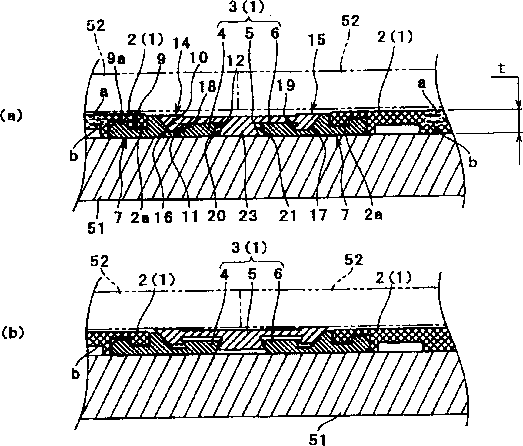
[0030] Next, a bobbin clamp device 1 according to an embodiment of the present invention will be described with reference to the drawings. figure 1 The main part of the bobbin clamping device 1 of the present embodiment is shown, and the cylindrical bobbin 52 for winding the yarn is detachably attached to the rotating cylinder 51 as the main body of the bobbin holder so that it can be held. state.

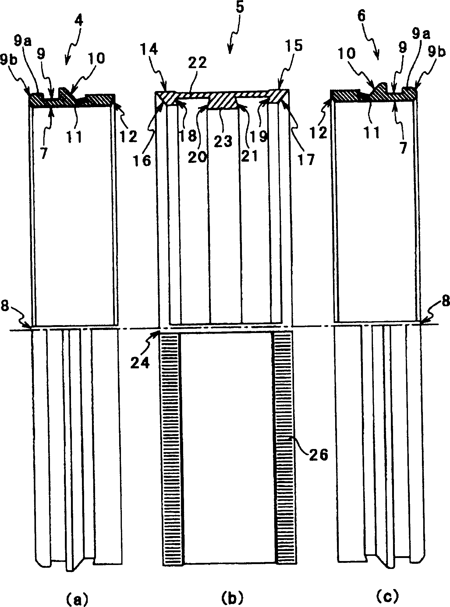
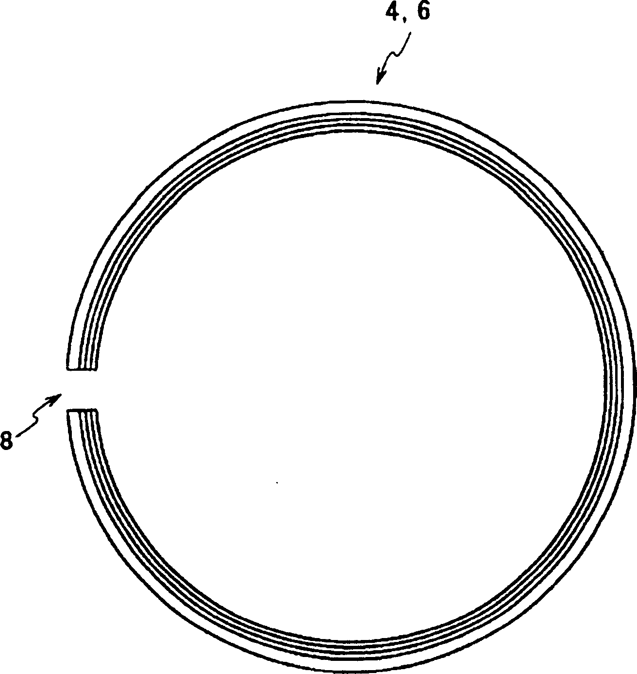
[0031] figure 1 The illustrated bobbin clamping device 1 includes an isolating ring 2 inserted on a rotating cylinder 51 and a clamping member 3 that holds or releases bobbins as the isolating ring 2 moves back and forth along the axis of the bobbin holder. figure 1 (a) shows the state where the clamp member 3 has released the bobbin 52, figure 1 (b) shows the state in which the bobbin 52 is held (clamped state).

[0032] Before describing the structure of the bobbin clamp device 1 in detail, the bobbin holder 50 using the bobbin clamp device 1 will be described. Figure 5 ...


PUM


Abstract

The invention discloses a bobbin chuck device capable of facilitating extracting a bobbin with a chuck piece certainly separated from the bobbin in releasing and extracting the bobbin from a bobbin holder, and capable of attaining wall thinning and high-speed handling of the bobbin holder. A chuck piece 3 includes a first member 5 for the bobbin 52 and second members (4, 6) for a rotating cylinder 51. The first member 5 and the second members (4, 6) relatively approach or are separated from each other in the axial direction of the rotating cylinder 51, so that the first member 5 and the second members (4, 6) are respectively energized toward or released from the bobbin 52 and the rotating cylinder 51. When the first member 5 and the second members (4, 6) are relatively moved so that both of the members may be respectively energization-released, both of the members are kept in mutual engagement, and an engagement part for separating the first member 5 from the bobbin 52 is provided on the first member 5 and the second members (4, 6) respectively.

Description

technical field [0001] The present invention relates to a bobbin chuck for use on the bobbin frame of a sliver winder for winding a sliver spun from a spinning machine, for inserting the bobbin on the bobbin frame . Background technique [0002] In the bobbin holder of such a sliver winding machine, a bobbin clamp for detachably holding a cylindrical bobbin for winding the sliver is provided on the outer periphery of the bobbin holder body composed of a rotating cylinder. device. In addition, as such a bobbin clamping device, in order to obtain a strong holding force that does not allow the bobbin to slide in the circumferential direction even under high-speed rotation, mechanical clamping devices are widely used. Japanese Patent Specification Laid-Open No. 6-67461 discloses a system that includes a spacer ring inserted on the outer periphery of a rotating cylinder as the bobbin holder body and that holds / releases the bobbin as the spacer ring moves back and forth in the a...

Claims


Application Information

Patent Timeline
IPC IPC(8): B65H54/547B65H54/54
Inventor 北山太
Owner MURATA MASCH LTD
Why Eureka
Try Eureka