Central buffer coupling device

A coupling device and housing technology, which is applied in the field of intermediate buffer coupling devices

Inactive Publication Date: 2003-10-22
克劳斯·莱本
View PDF1 Cites 7 Cited by
  • Summary
  • Abstract
  • Description
  • Claims
  • Application Information

AI Technical Summary

Problems solved by technology

The return flow of the damping medium is braked, but not optimally, by the closing non-return valve of the bypass bore

Method used


Image

  • Central buffer coupling device
  • Central buffer coupling device
  • Central buffer coupling device

Examples


Embodiment Construction

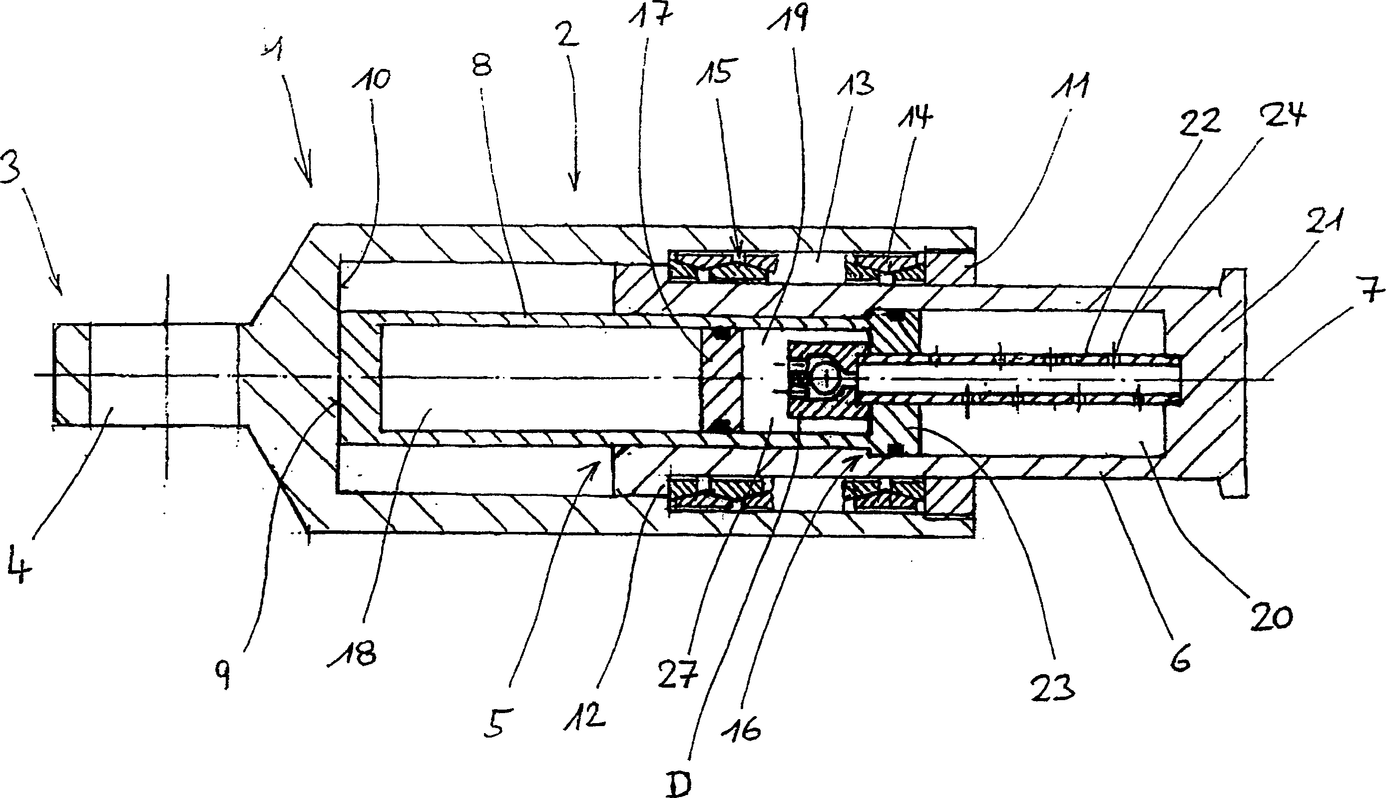
[0029] according to figure 1 The intermediate buffer coupling device comprises a housing 1 with a cylindrical section 2 and a connecting section 3 . In this known manner, the connection section 3 has a suitable eye ring 4 for receiving a ball joint, which allows the housing 1 not only to travel in a horizontal plane (curved lines) with respect to a locomotive equipped with an intermediate buffer coupling. ) and swings in a vertical plane (pop-in).

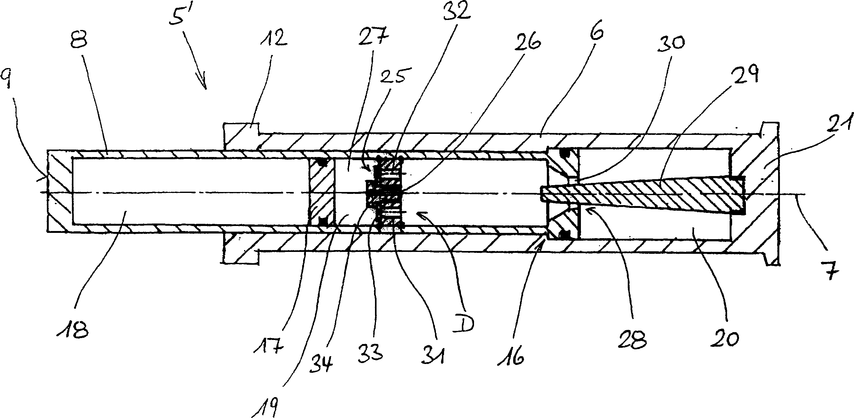
[0030] A damping sleeve 5 is arranged inside the cylindrical section 2 in the housing 1 . This damping sleeve comprises a cylindrical part 6 as main part and a hollow piston 8 which is guided displaceably along an axis 7 within this cylindrical part 6 . The hollow piston 8 is supported with its end face 9 on a bearing face 10 of the housing 1 . A cylindrical part 6 of the damping sleeve 5 projects out of the housing 1 ; this cylindrical part 6 is guided displaceably in the housing 1 along an axis 7 . For this purpose, on the on...


PUM


Abstract

A central buffer coupling device comprises a housing (1) and a damper cartridge (5, 5', 5''). The damper cartridge includes a cylinder component (6) and a hollow piston (8) guided axially in the cartridge; the damper cartridge further includes a hydraulic damping unit having a working chamber (20), the working chamber is connected to an overfall chamber (19) through a throttle flow path, the overfall chamber is disposed in the hollow piston (8) and is separated from an elastic chamber (18) by a separating piston (17); the working chamber (20) is connected to a balance chamber (27) through a flow path having an asymmetry throttle device (D), the changing trend of the balance chamber is reverse with the changing trend of the cubage of the working chamber, the resistance that the asymmetry throttle device applies to the damping medium flowing from the balance chamber to the working chamber is larger than the resistance for the reverse flow of the damping medium; the asymmetry throttle device is connected in series with a throttle valve in the flow path for connecting the working chamber and the overfall chamber.

Description

technical field [0001] The invention relates to an intermediate buffer coupling device comprising a housing and a damping sleeve, the intermediate buffer coupling device has the following characteristics: [0002] The housing has a cylindrical section and a connecting section; [0003] The damping sleeve comprises as main part a cylindrical part and a hollow piston guided axially displaceably in the cylindrical part, the hollow piston protruding from the cylindrical part at the end; [0004] The damping sleeve is accommodated in the cylindrical section of the housing in such a way that one main part bears axially on a bearing surface of the housing, while the other main part protrudes from the housing on this guided axially displaceably in the housing; [0005] accommodating a first elastic unit in an annular chamber between the damping sleeve and the cylindrical section of the housing; [0006] The damping sleeve comprises a hydraulic damping unit with a working chamber wh...

Claims


Application Information

Patent Timeline
Patent Type & Authority Applications(China)
IPC IPC(8): B61G9/08B61G11/12
CPCB61G9/08B61G11/12F16F9/063F16F9/067F16F9/49
Inventor 克劳斯·莱本伯恩哈德·斯塔克
Owner 克劳斯·莱本
Why Eureka
Try Eureka