Modular manifold for heating and sanitary systems

A modular, manifold technology, applied in piping systems, pipes, branch pipelines, etc., can solve the problems of using tools, time-consuming plastic manifolds, etc., to reduce assembly time, reduce pressure loss, and reduce weight.

Inactive Publication Date: 2003-10-29
贾科米尼公开有限公司
View PDF0 Cites 16 Cited by
  • Summary
  • Abstract
  • Description
  • Claims
  • Application Information

AI Technical Summary

Problems solved by technology

[0012] However, apart from the simplification obtained in terms of inventory, these same modular elements produced by injection molding have practically the same disadvantages as mentioned above compared to metal manifolds produced by casting
[0013] Furthermore, the assembly of the plastic manifold is time consuming and requires the use of tools

Method used


Image

  • Modular manifold for heating and sanitary systems
  • Modular manifold for heating and sanitary systems
  • Modular manifold for heating and sanitary systems

Examples


Embodiment 21

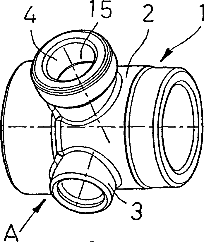
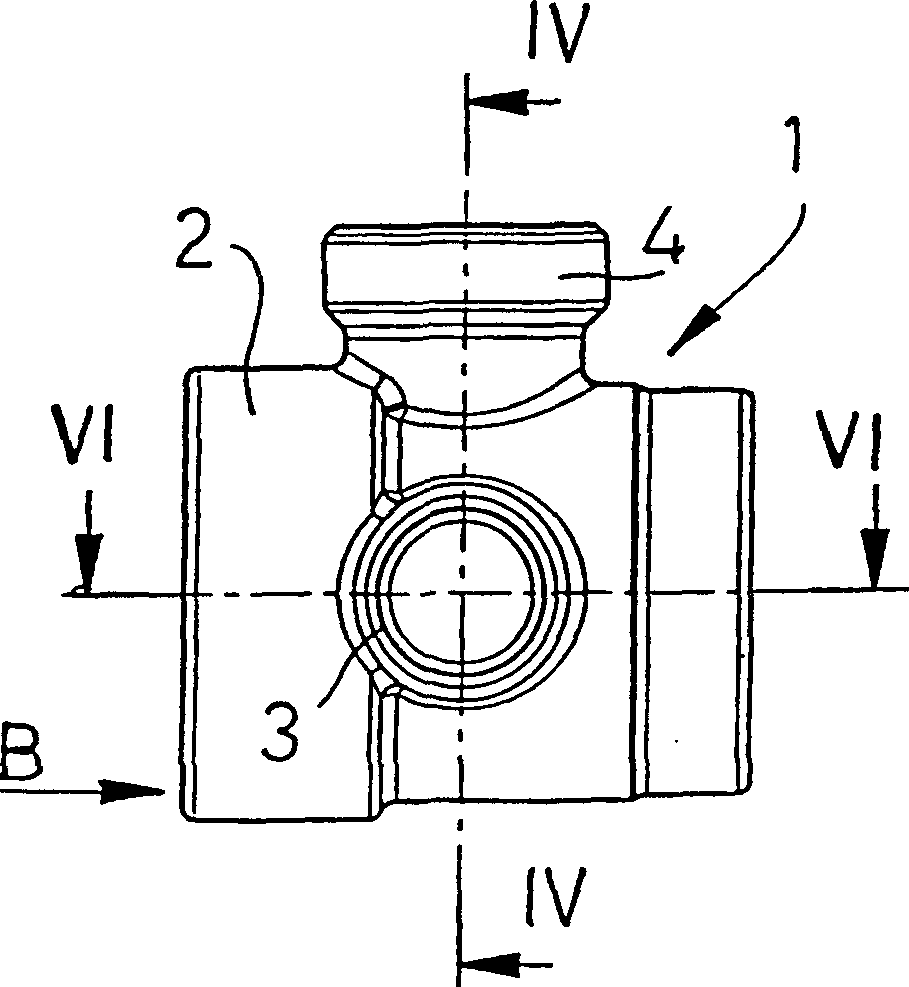
[0080] The tap 4 can also be constructed like the tap 4A, ie a fixture for mounting metal pipes, plastic pipes, composite or multilayer pipes, etc.

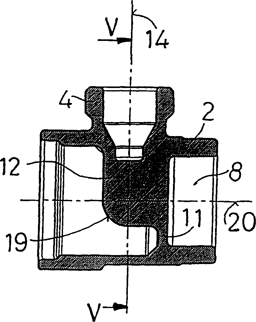
[0081] In order to enhance the reduction of pressure losses caused by friction and indirectly achieve better dimensions and better efficiency of the pipes of heating or sanitary systems, no Boss 12 and first and second cup-shaped end chambers 6 , 8 , while the latter of said connecting pipe 12 have substantially the same inner diameter, so that inside module body 2 a substantially cylindrical straight-through pipe 16A is obtained.

[0082] Further structural features of the manifold modules 70, 71 and 80 can be deduced from FIGS. 7 to 13 and their above description.

[0083] In another aspect of the present invention, a flow meter or the like or a thermostatic element or a piston head end of the automatic control switch 34 may also be installed in the adjusting joint 3 of the installation switch 34 .

[0084] Each of the two com...


PUM


Abstract

Improved modular manifold (40) for heating and sanitary systems, comprising tubular manifold modules (21; 50, 51, 60, 61; 70, 71, 80) having integrally formed End coupling means (22, 23; 53, 54), and or only a tap (4), or a tap (4) and a regulating tap (3) for respectively receiving the pipes and switchgear of the split circuit ( 62). A metal preform (1) is provided for producing said manifold module (21; 50, 51, 60, 61; 70, 71, 80) by hot pressing and chip forming machining steps. Plastic manifold modules (21; 50, 51, 60, 61; 70, 71, 80) may also be injection molded.

Description

Technical field: [0001] The present invention relates to improved modular manifolds for heating and sanitary systems, manifold modules and module blanks according to the preceding characterizing parts of claims 1 , 13 and 16 . [0002] The invention also relates to a method of manufacturing a blank according to the preamble of claim 20 . Background technique: [0003] It is known to use monolithic manifolds in heating and sanitary systems for a large number of heating and water distribution circuits that divide the feed pipes, also collect the discharge of said circuits and route the latter into the return pipe of the heating or water system. [0004] The known manifold has a tubular body with a number of joint couplings formed by adjustment joints, comprising respectively a switch and a tap with an external control button. The regulating and diverting joint is in fluid communication with the blocking port that cooperates with the straight-through pipe of the manifold and t...

Claims


Application Information

Patent Timeline
Patent Type & Authority Applications(China)
IPC IPC(8): F16K27/00F16L41/02F17D1/00
CPCF16K27/003F16L41/02F16L41/03Y10T137/87885
Inventor 马里奥·贾科米尼
Owner 贾科米尼公开有限公司
Why Eureka
Try Eureka