Piston pin mounting structure for sealed compressor

A mounting structure, piston pin technology, applied to parts of pumping devices for elastic fluids, mechanical equipment, machines/engines, etc., to achieve the effects of preventing deformation, long-term fixed bonding, and suppressing the tendency to rotate

Inactive Publication Date: 2003-11-12
LG ELECTRONICS (TIANJIN) APPLIANCES CO LTD
View PDF0 Cites 0 Cited by
  • Summary
  • Abstract
  • Description
  • Claims
  • Application Information

AI Technical Summary

Problems solved by technology

[0006] But the prior art that the piston pin is fixed on the piston by the clamp method has the following disadvantages: the piston pin 7' is columnar, and the outer peripheral surface of the piston pin 7' is made of a curved surface

Method used


Image

  • Piston pin mounting structure for sealed compressor
  • Piston pin mounting structure for sealed compressor
  • Piston pin mounting structure for sealed compressor

Examples


Embodiment Construction

[0019] The piston pin installation structure of the hermetic compressor of the present invention will be further described in detail in conjunction with the accompanying drawings and specific embodiments:

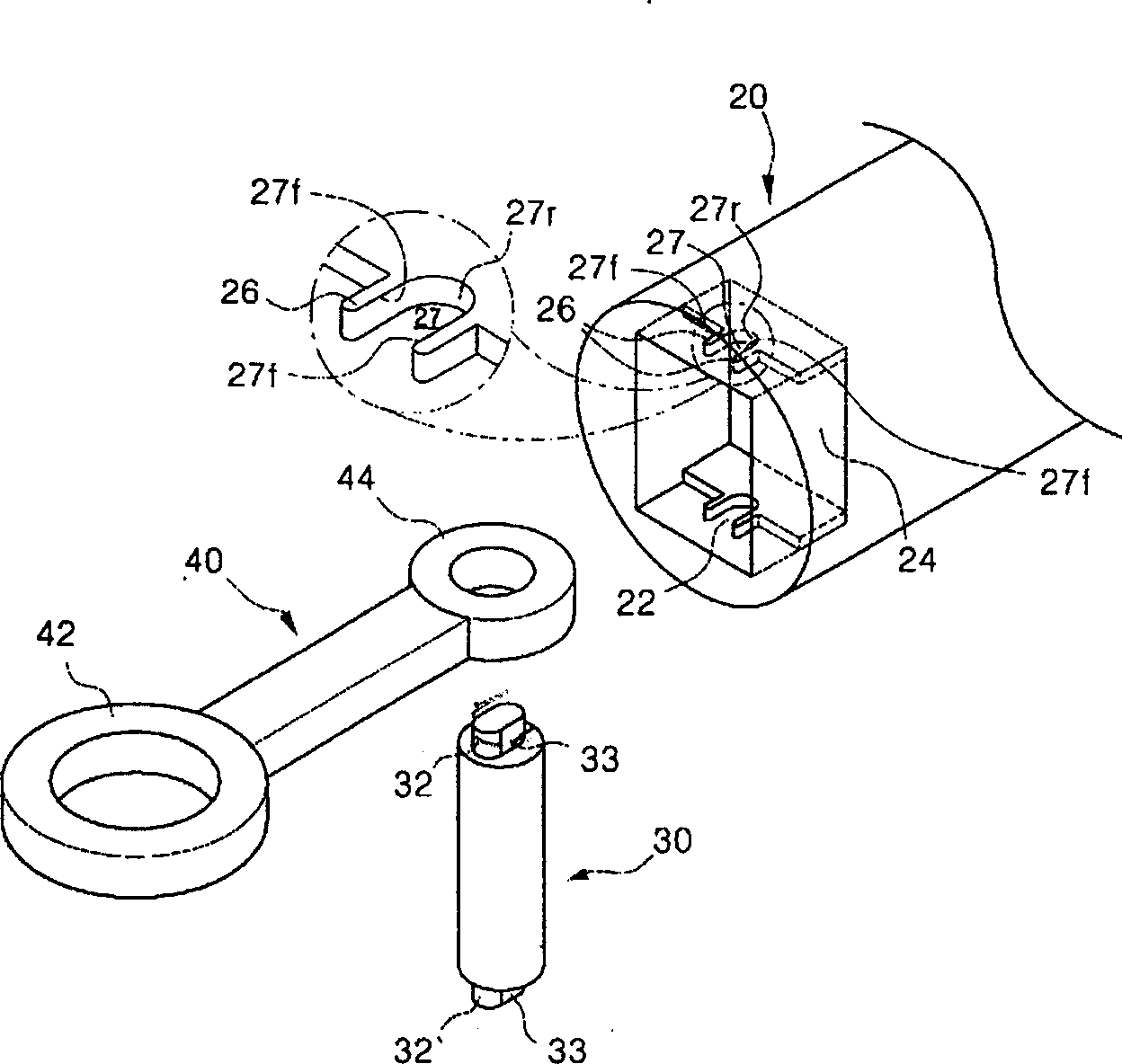
[0020] like image 3 , 4 As shown, the piston 20 performs rectilinear reciprocating motion inside the compression chamber, and the piston 20 forms a cylinder shape. A connection space 22 is formed inside the rear end of the piston 20 , and the connection space 22 is formed opening to the rear of the piston 20 . Inside the connection space 22 is formed a collision preventing portion 24 that prevents collision between the small end portion 44 of the connecting rod 40 and the piston 20 . The anti-collision portion 24 is recessed inwardly in the connection space 22 and is located at one end of the small end portion 44 .

[0021] The upper and lower parts of the anti-collision part 24 are formed with a bandage part 26 , and the bandage part 26 plays a role of fixing the pisto...


PUM


Abstract

The present invention discloses a piston pin mounting structure of closed compressor, which utilized the plastic deformation produced by fastening hoop portion to make the piston pin be fixed and combined on the piston, and make the piston pin can not be rotated and firming fixed on the pistonl. In order to implement firm combination the fixing combination portion can be respectively formed on two end portions of piston pin, and on the fixing combination portion a fixing stopping surface is formed, and on the mounting groove of piston a plane portion correspondent to fixing stopping surface is formed, and said combination of fixing sotpping surface and plane portion can be used for implementing the goal of preventing the piston pin from producing rotation, and can implement their firming connection to raise performance of compressor.

Description

technical field [0001] The invention relates to a hermetic compressor, in particular to an invention about a piston pin installation structure of a hermetic compressor. Background technique [0002] Generally, the internal structure of the hermetic compressor of the prior art is as figure 1 As shown, the upper container 1 t and the lower container 1 b constitute an airtight container 1 , and a frame 2 is provided inside the airtight container 1 . A stator 3 is fixed on the frame 2, and the frame 2 is supported inside the airtight container 1 by a spring 2S. A crankshaft 5 is provided through the center of the frame 2 . A rotor 4 is provided integrally with the crankshaft 5 , and the crankshaft 5 rotates together by electromagnetic interaction between the rotor 4 and the stator 3 . The upper end of the crankshaft 5 is provided with an eccentric pin 5 b eccentrically arranged with respect to the rotation center of the crankshaft 5 . A counterweight 5c is provided on the op...

Claims


Application Information

Patent Timeline
Patent Type & Authority Applications(China)
IPC IPC(8): F04B27/08F04B53/14
Inventor 卓璟植
Owner LG ELECTRONICS (TIANJIN) APPLIANCES CO LTD
Why Eureka
Try Eureka