Method for mfg. electric connector containing multi-conducting terminals and metal frame by plugging shaping method

A technology of conductive terminals and metal frames, which is applied in the field of insert molding to manufacture an electrical connector including a large number of conductive terminals and metal frames, which can solve the problems of terminal spacing or coplanarity changes, deformation, and reduced connector precision.

Inactive Publication Date: 2003-12-03
MOLEX INC
View PDF0 Cites 3 Cited by
  • Summary
  • Abstract
  • Description
  • Claims
  • Application Information

AI Technical Summary

Problems solved by technology

However, this molding method tends to have the problem that the contact part of the conductive terminal is not easy to keep on the same plane during injection molding. The wall of the casing, and before the injection molding of the molten resin, because the wall has not yet been formed, there is a gap between the conductive terminal and the wall of the mold cavity that can accommodate the molding of the wall. Therefore, under the injection pressure, the molten The material will produce stresses directly on the terminals, causing changes or distortions in terminal spacing or coplanarity that reduce the expected precision of the connector

Method used


Image

  • Method for mfg. electric connector containing multi-conducting terminals and metal frame by plugging shaping method
  • Method for mfg. electric connector containing multi-conducting terminals and metal frame by plugging shaping method
  • Method for mfg. electric connector containing multi-conducting terminals and metal frame by plugging shaping method

Examples


Embodiment Construction

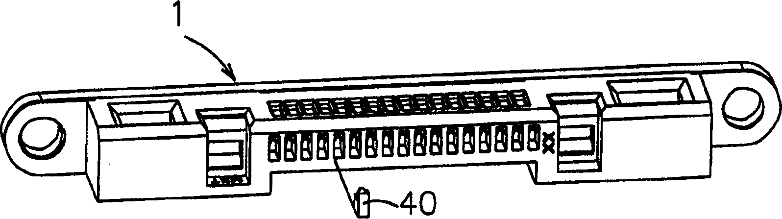
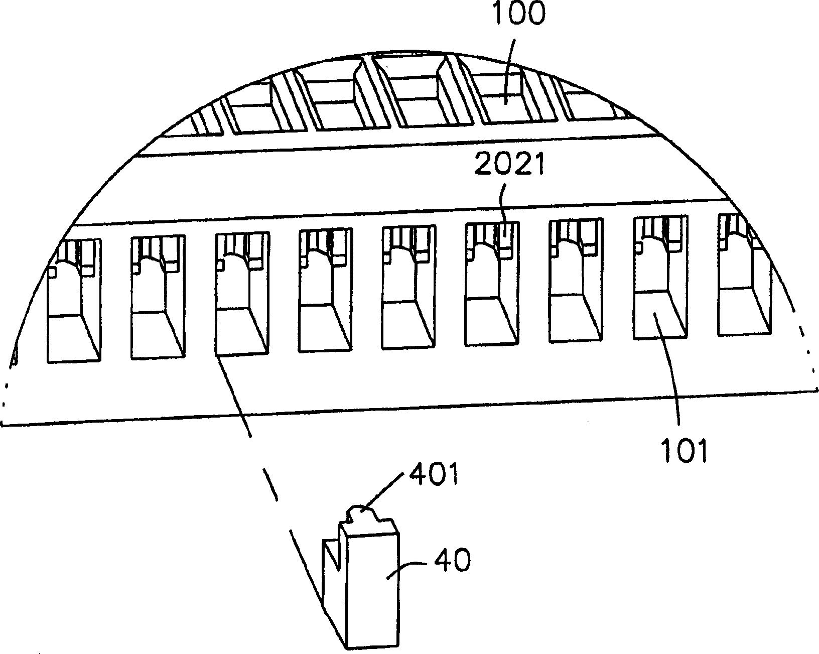
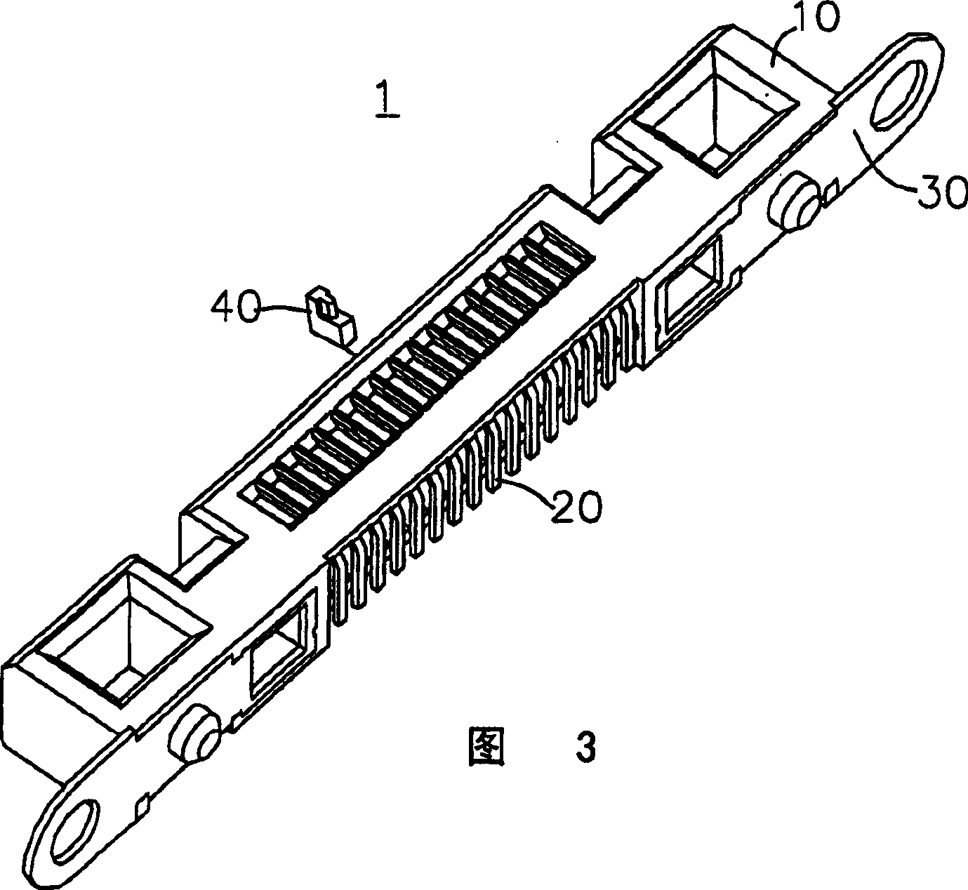
[0022] Hereinafter, a preferred embodiment will be used to illustrate the implementation of the present invention. See you first figure 1 -4, where Figure 4 shows the position of the conductive terminal 20 and the metal frame 30 when they are placed in the mold cavity as the core during insert molding, figure 1 , 3 is the connector 1 after the insulating housing has been formed. As can be seen from the second figure, except for the surface for soldering on the circuit board, the insulating housing 10 surrounds most of the surface of the conductive terminal 20 and the metal frame 30. In addition, a slot 100 is formed at the contact portion 202 corresponding to each terminal, so that the mating connector can be electrically connected to the contact portion 202.

[0023] figure 1 The connector 1 and a terminal portion holder 40 in a separated state, that is, in the position shown in this figure, the connector 1 is plugged with the mating connector upward. As shown in FIG. 6, each...


PUM


Abstract

An insertion method for manufacturing the electric connector containing multiple electric conducting terminals and a metallic framke includes assembling said terminals and metallic frame together, putting it in mould cavity, inserting the detachable first and second fixers between adjacent terminals from their free ends and tail ends, espectively, and filling the fused resin in the mould cavity to form an insulating casing.

Description

Technical field [0001] The present invention relates to a method for manufacturing an input / output connector of a computer or communication device by insert molding method, and more particularly to an insert molding method, in which the electrical connector is formed by injection molding an insulating housing material, And during the formation of the connector insulating housing, the contact parts of a set of conductive terminals pre-placed in the mold cavity are kept coplanar, and the connector insert molding method is maintained in which the distance between the terminals is equal. Background technique [0002] In the past, insert-molding was used in the manufacture of connectors, so that conductive terminals, metal frames, and insulating housings can be formed into an integral unit by injecting molten resin into a cavity pre-installed with conductive terminals and metal frames. structure. However, this molding method is prone to the problem that the contact parts of the conduc...

Claims


Application Information

Patent Timeline
Patent Type & Authority Applications(China)
IPC IPC(8): B29C39/00H01R43/18
Inventor 谢光荣
Owner MOLEX INC
Why Eureka
Try Eureka